Frequency-scalable shockline-based signal-source extensions

a shockline and frequency range technology, applied in resistance/reactance/impedence, digital variable/waveform display, instruments, etc., can solve the problem of increasing the noise figure of the sampler due to image-response conversion, providing equivalent-time sampling at the expense of increased conversion loss, and reducing the output voltage of the sampler. , to achieve the effect of reducing or increasing the fall time of the output voltage waveform, reducing or increasing the frequency scalability of th

Inactive Publication Date: 2011-12-15
ANRITSU CORP
View PDF11 Cites 11 Cited by
  • Summary
  • Abstract
  • Description
  • Claims
  • Application Information

AI Technical Summary

Benefits of technology

[0025]Scaling to adjust electrical performance vs. frequency is accomplished by the use of multiplexing as well as frequency scaling. Frequency scaling is accomplished to fine tune the frequency vs. performance of an individual NLTL. Multiplexing allows the output of a single or multiple NLTLs to be fine tuned. Multiplexing can be accomplished using couplers or switches.
[0026]Frequency scalability of an NLTL is accomplished by increasing or decreasing the Bragg frequency of an NLTL, thus tuning its millimeter-wave harmonic content over a desired frequency range. The Bragg cutoff frequency of the NLTL can be increased or decreased by changing the spacing between varactor diodes of the NLTL, so as to either reduce or increase the fall time of its out

Problems solved by technology

Equivalent-time sampling, however, is provided at the expense of increased conversion loss.
Commercial SRDs are traditionally limited to LO inputs having frequencies that do not exceed a few hundred MHz.
This limitation is a fundamental one in the context of microwave and millimeter-wave VNAs since it requires that a high harmonic number N be used in the down-conversion process, resulting in an increase in the noise figure of the sampler due to image-response conversion.
In addition, the use of a high harmonic number increases the number of spurious receiver responses and can reduce the effective dynamic range of a VNA.
Another fundamental limitation in an SRD-based VNA is the RF leakage between channels.
Thus with a purely passive network, there is an isolation limitation (sig

Method used


Image

  • Frequency-scalable shockline-based signal-source extensions
  • Frequency-scalable shockline-based signal-source extensions
  • Frequency-scalable shockline-based signal-source extensions

Examples


Embodiment Construction

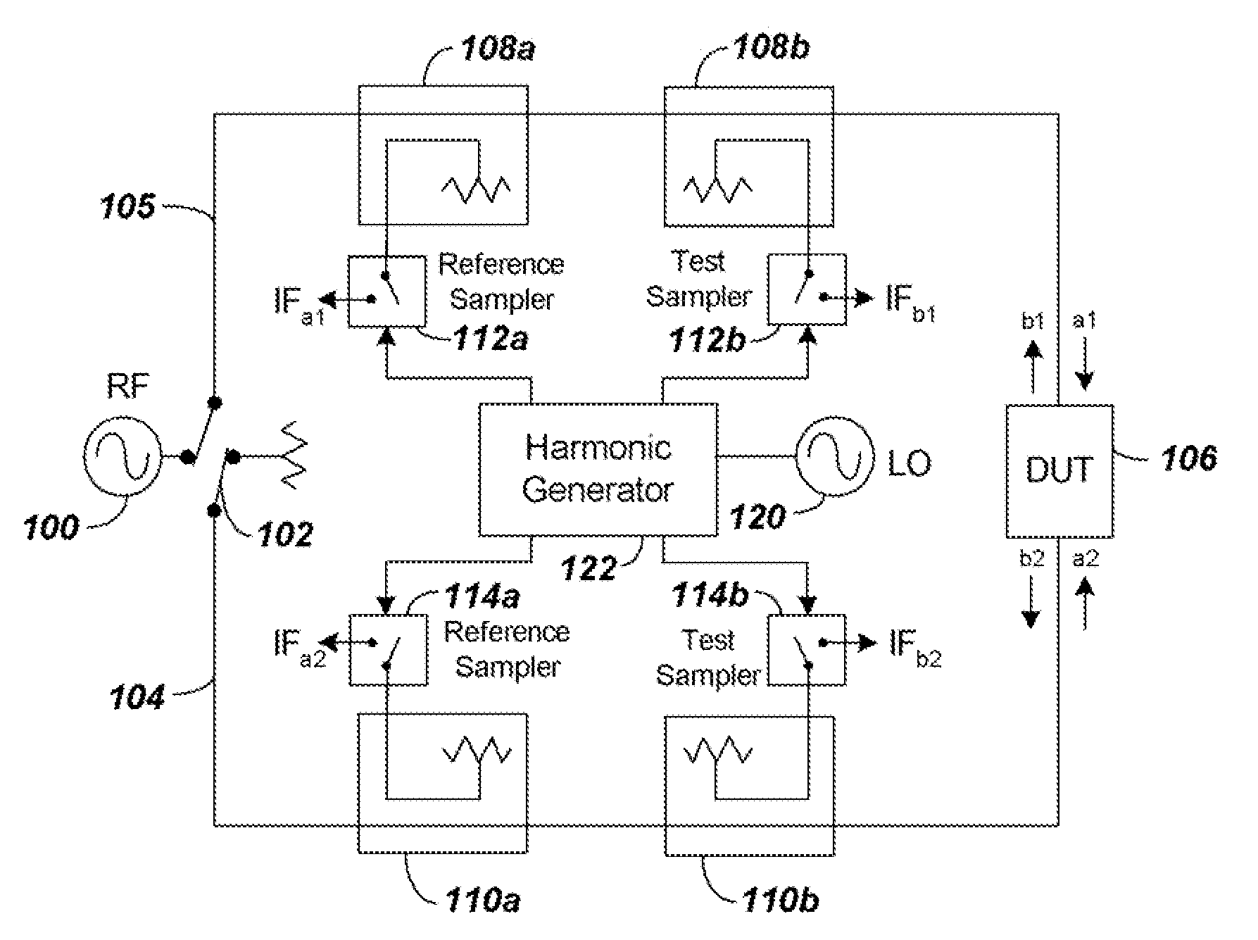
[0047]Components of embodiments of the present invention provide a system using NLTLs to extend the frequency range of an RF source. The RF source extension system can be used in conjunction with a VNA system that uses NLTL-based samplers that receive and downconvert broadband high frequency signals. To facilitate understanding of the use of the RF source extension system in embodiments of the present invention, a NLTL-based sampler system is first described to follow.

I. Sampler Based NLTL System

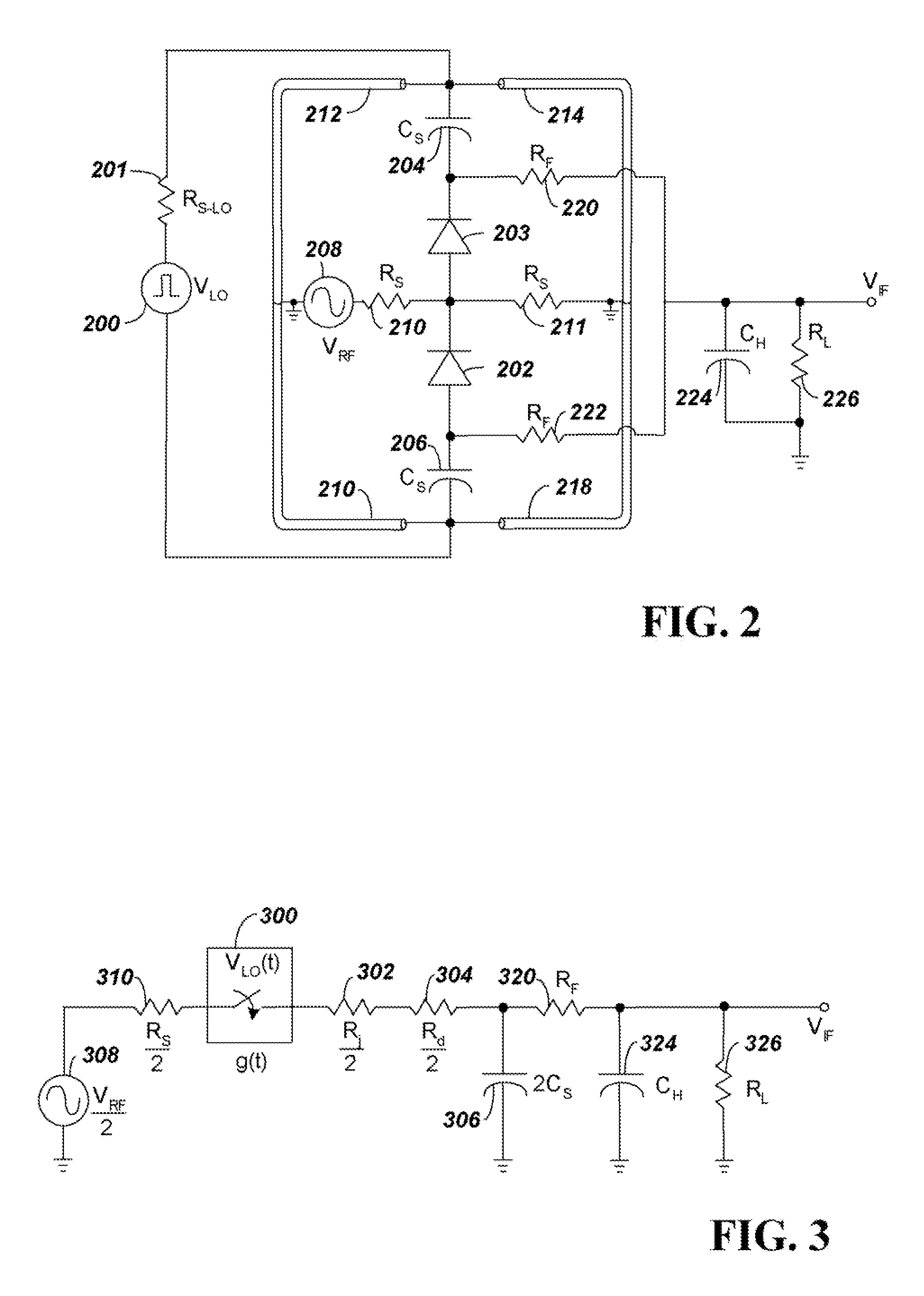
[0048]To accomplish frequency scaling when using NLTLs in embodiments of the present invention, it is initially realized that by changing gating time, Tg, frequency vs. RF conversion efficiency can be controlled. A reduction in the gating time Tg of the sampling Schottky diodes can be shown to provide an increase in RF bandwidth at the expense of reduced conversion efficiency. Adjusting the Bragg frequency of the NLTL as well as the length of the shorted stubs in the sampler changes this gat...


PUM


Abstract

A system is provided using one or more shocklines or non-linear transmission lines (NLTLs) to extend the bandwidth of an RF signal source. Extension of the RF bandwidth is achieved by means of multiplexing as well as frequency scaling. Frequency scaling tailors the performance of each NLTL for operation in a particular output frequency band(s) by adjusting the varactor spacing in the NLTL. Multiplexing amalgamates the output frequency bands of one or more NLTLs, thus resulting in a broad output frequency range.

Description

CLAIM FOR PRIORITY[0001]This application is a continuation-in-part of application Ser. No. 12 / 813,337 filed on Jun. 10, 2010, entitled “Frequency-Scalable Shockline-Based VNA,” which is incorporated by reference herein in its entirety.BACKGROUND[0002]1. Technical Field[0003]The present invention relates to components that extend the frequency range of a Vector Network Analyzer (VNA). More particularly, the present invention relates to high-frequency components such as non-linear transmission lines or shocklines that can be used to extend the RF source frequency of sampler-based VNAs to operate at high frequencies.[0004]2. Related ArtA. High-Frequency Sampler-Based VNA Receivers in General[0005]Sampler-based VNA receivers make use of equivalent-time sampling to down-convert RF stimulus and response signals to lower intermediate-frequency (IF) signals. In effect, the samplers “time-stretch” coupled versions of RF signal waves incident on and reflected from a device under test (DUT). T...

Claims


Application Information

Patent Timeline
IPC IPC(8): G01R23/16
CPCG01R31/2841G01R27/32
Inventor NOUJEIM, KARAM MICHAELMARTENS, JON S.
Owner ANRITSU CORP
Why Eureka
Try Eureka