Aerodynamic dead zone-less triple rotors integrated wind power driven system

a technology of wind power driven system and dead zone, which is applied in the direction of rotors, marine propulsion, vessel construction, etc., can solve the problems of reduced total rotational force, limited force generated, and reduced rotational force of two or more rotors, so as to reduce the total rotational force and avoid the drag force created by the different tip speed

Inactive Publication Date: 2011-12-15
SHIN CHAN +1
View PDF8 Cites 19 Cited by
  • Summary
  • Abstract
  • Description
  • Claims
  • Application Information

AI Technical Summary

Benefits of technology

[0010]The control rotor increases the rotational speed of both auxiliary rotor in the up-wind position and main rotor in the down-wind position during low wind speed as well as during rated wind speed.
[0011]Another object of the present invention is to provide a flexible electromagnetic torque coupling where the rotational force of two or more rotors of different RPM is not limited by the gear ration of the RPMs of each rotors.
[0012]When the tip speed ratio of each rotors are different, rotation of one rotor acts as a drag force on each other thereby decreasing the total rotational force. Coupling of electromagnetic torque of the current invention is flexible and is not dependent on the gear ratio of the rotors and the drag force created by the different tip speed is avoided.

Problems solved by technology

Another disadvantage involves the coupling the rotational forces of two or more rotors with different RPMs, where the force generated is limited by the gear ratio of each rotor's RPM and the total rotational force is decreased by the drag force created between the rotors of different tip speed rotor.
Another challenge to a developer of a wind turbine system is avoiding aerodynamic interference between the counter-rotating rotors.

Method used


Image

  • Aerodynamic dead zone-less triple rotors integrated wind power driven system
  • Aerodynamic dead zone-less triple rotors integrated wind power driven system
  • Aerodynamic dead zone-less triple rotors integrated wind power driven system

Examples


Embodiment Construction

Triple Rotor System

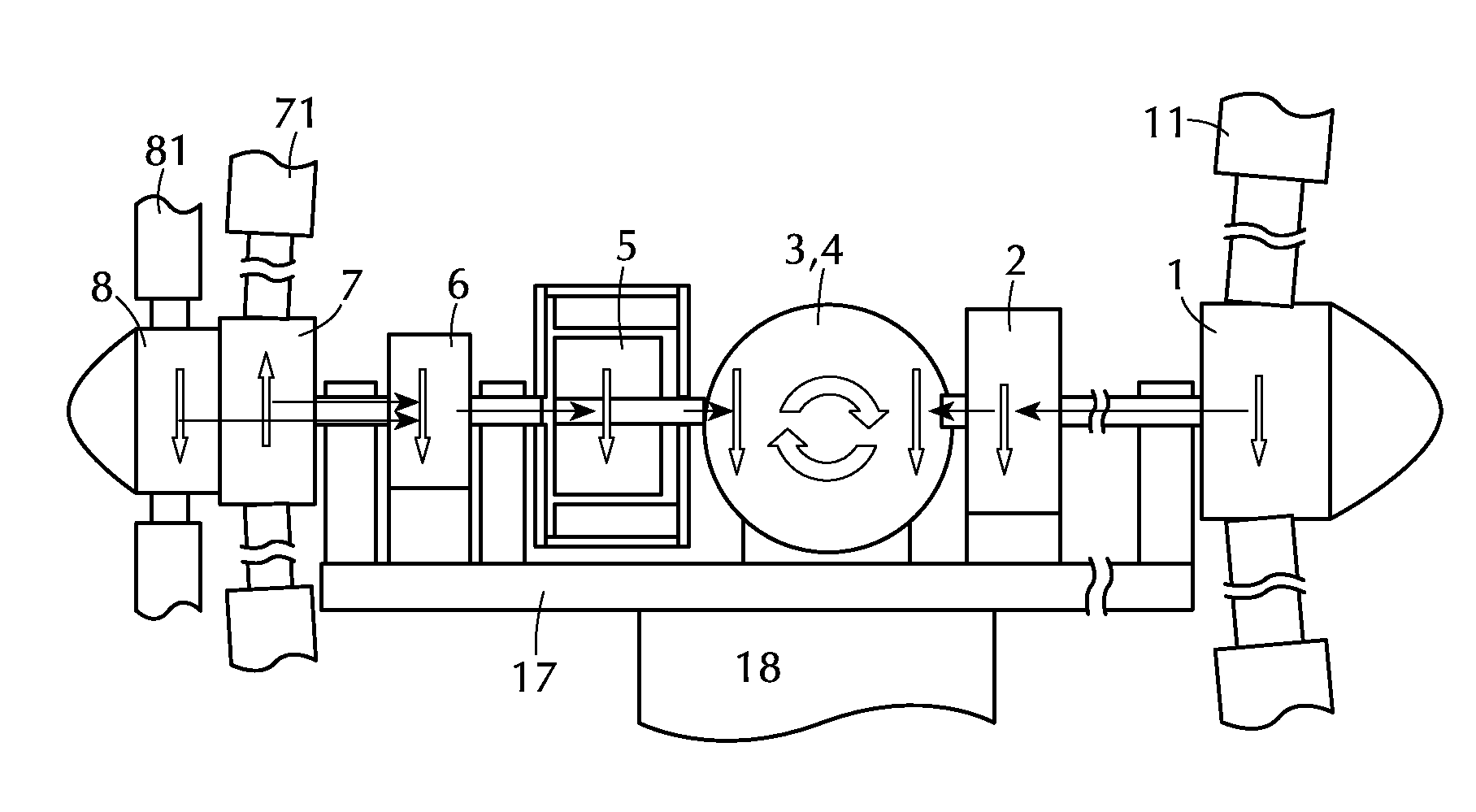
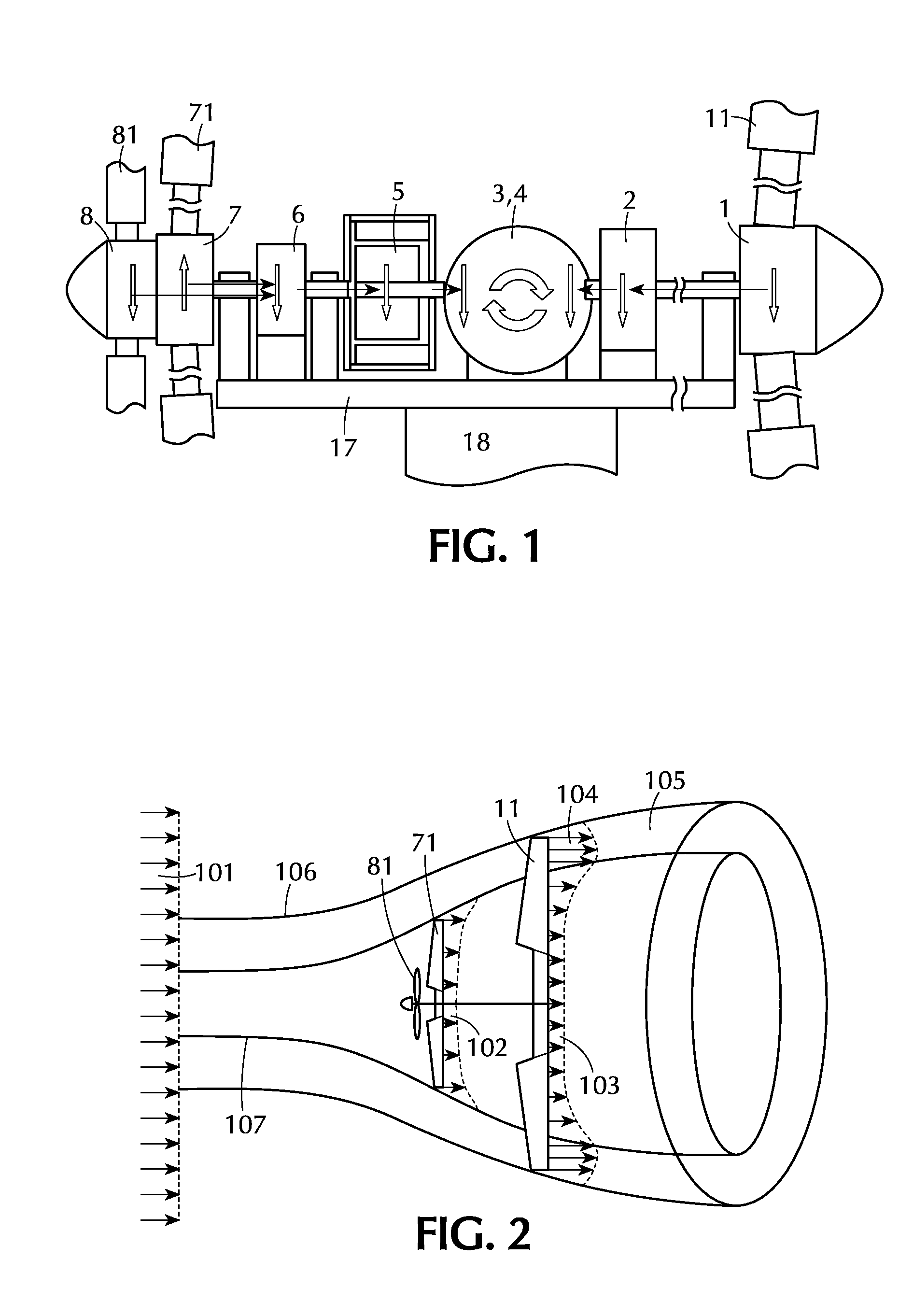
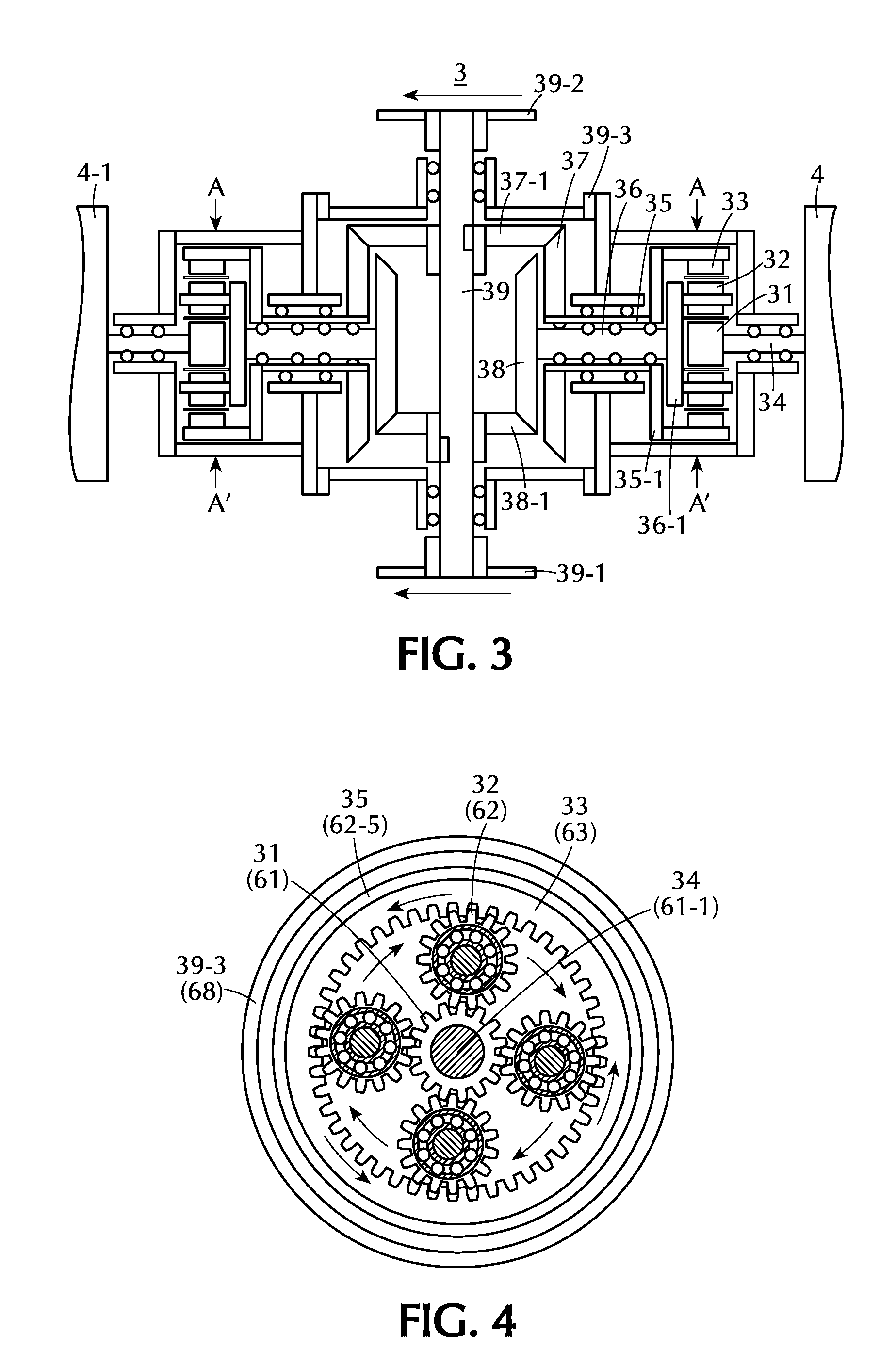
[0026]FIG. 1 shows overall system of the present invention. The present invention can be divided into seven parts. Part 1 in a down wind position comprises of main rotor 11 (“MR”) and its hub 1. Part 2 comprises of a gear box 2 which increases the speed of MR 11. Part 3 comprises of a gear box 3 which combines the rotational forces of control rotor 81 (“CR”), auxiliary rotor 71 (“AR”) and MR 11.

[0027]Part 4 comprises of twin generators 4, 4-1. Part 5 comprises of the auxiliary generator 5 which combines rotational forces of CR 81 and AR 71. Part 6 comprises of dual axis input gear box 6 which combines the rotational forces of CR 81 and AR 71. Part 7 comprises of CR hub 7 and AR hub 8 in a up wind position.

Aerodynamic Dead Zone

[0028]A wind turbine obtains its power input by converting the force of the wind into a torque on the rotor blades. The amount of energy which the wind transfers to the rotor depends on the density of the air, the rotor area, and the wind spe...


PUM


Abstract

The present invention relates to an aerodynamic dead zone-less triple-rotor integrated wind power driven system wherein control rotor 81 disposed at up-wind is rotated at a high speed. It induced the air flowing into the hub of extenders 71 of the auxiliary rotor 71 to the outside of the extenders 71-1 of the auxiliary rotor 71, thereby forming an aerodynamic annular stream tube zone and increasing the air density therein, the main rotor 11 disposed at down-wind, is aerodynamically accelerating and improving the system efficiency. In addition, the rotor 52 and stator 51 of the electromagnetic attraction dragging rotational torque of the auxiliary generator by the load assists to rotate main rotor 11, thereby the triple rotors integrating rotational torque generates the twin generators 4 and 4-1″ of the wind turbine.

Description

CROSS-REFERENCE TO RELATED APPLICATIONS[0001]This application claims the benefit of U.S. Provisional Application No. 61 / 353,679 filed Jun. 11, 2010, which is incorporated herein in its entirety.FIELD OF THE DISCLOSURE[0002]The present invention relates generally to a wind turbine system for generating electricity and more specifically to a wind turbine system for generating electricity that includes two up-wind rotors and one down-wind rotor structure.BACKGROUND OF THE INVENTION[0003]Existing large scale wind turbine systems for utilizing wind energy to generate electricity have certain disadvantages.[0004]For example, when the diameter of a wind turbine rotor exceeds twelve (12) meters, the wind input at its center has no effect on the rotation of the rotor thereby creating “an aerodynamic dead zone.” Accordingly, a large scale wind turbine system has its corresponding large aerodynamic dead zone.[0005]Another disadvantage involves the coupling the rotational forces of two or more ...

Claims


Application Information

Patent Timeline
Patent Type & Authority Applications(United States)
IPC IPC(8): F03D11/00
CPCF03D1/025F05B2240/2213Y02E10/72H02K7/1838F05B2260/40311F05B2220/706F03D15/00F03D1/02F03D9/25F03D15/10
Inventor SHIN, CHANSHIN, IKE
Owner SHIN CHAN
Why Eureka
Try Eureka