Displacement detecting device

a technology of displacement detection and detection device, which is applied in the direction of measurement device, converting sensor output optically, instruments, etc., can solve the problems of reducing detection accuracy, detecting errors, and changing the optical path length of each beam of light, so as to eliminate the surface roughness of diffraction grating error, accurate detection, and improved detection accuracy

Active Publication Date: 2011-12-22
DMG MORI SEIKI CO LTD
View PDF3 Cites 24 Cited by
  • Summary
  • Abstract
  • Description
  • Claims
  • Application Information

AI Technical Summary

Benefits of technology

[0017]With the displacement detecting device according to the present invention, by the reflectors, the output angle of the 1st-order diffracted lights diffracted by the diffraction grating and the incidence angle of the 1st-order diffracted lights incident again on the diffraction grating are set to be different from each other. Thus, the optical path of the 2nd-order diffracted lights diffracted twice is not parallel to either the optical path of the 1st-order diffracted lights or the optical path of the light incident from the light source onto diffraction grating. As a result, the possibility tha

Problems solved by technology

Thus, there is a concern that, in the 2nd-order diffracted light diffracted twice by the diffraction grating, unnecessary stray light caused by multiple reflection of each component might be superimposed on the interference light.
As a result, noise might be cased due to superimposition of the unnecessary

Method used


Image

  • Displacement detecting device
  • Displacement detecting device
  • Displacement detecting device

Examples


first embodiment

1. First Embodiment

[0036]First, the configuration of a displacement detecting device according to a first embodiment (referred to as “present embodiment” hereinafter) of the present invention will be described below with reference to FIGS. 1 to 3.

1-1. Configuration Example of Displacement Detecting Device

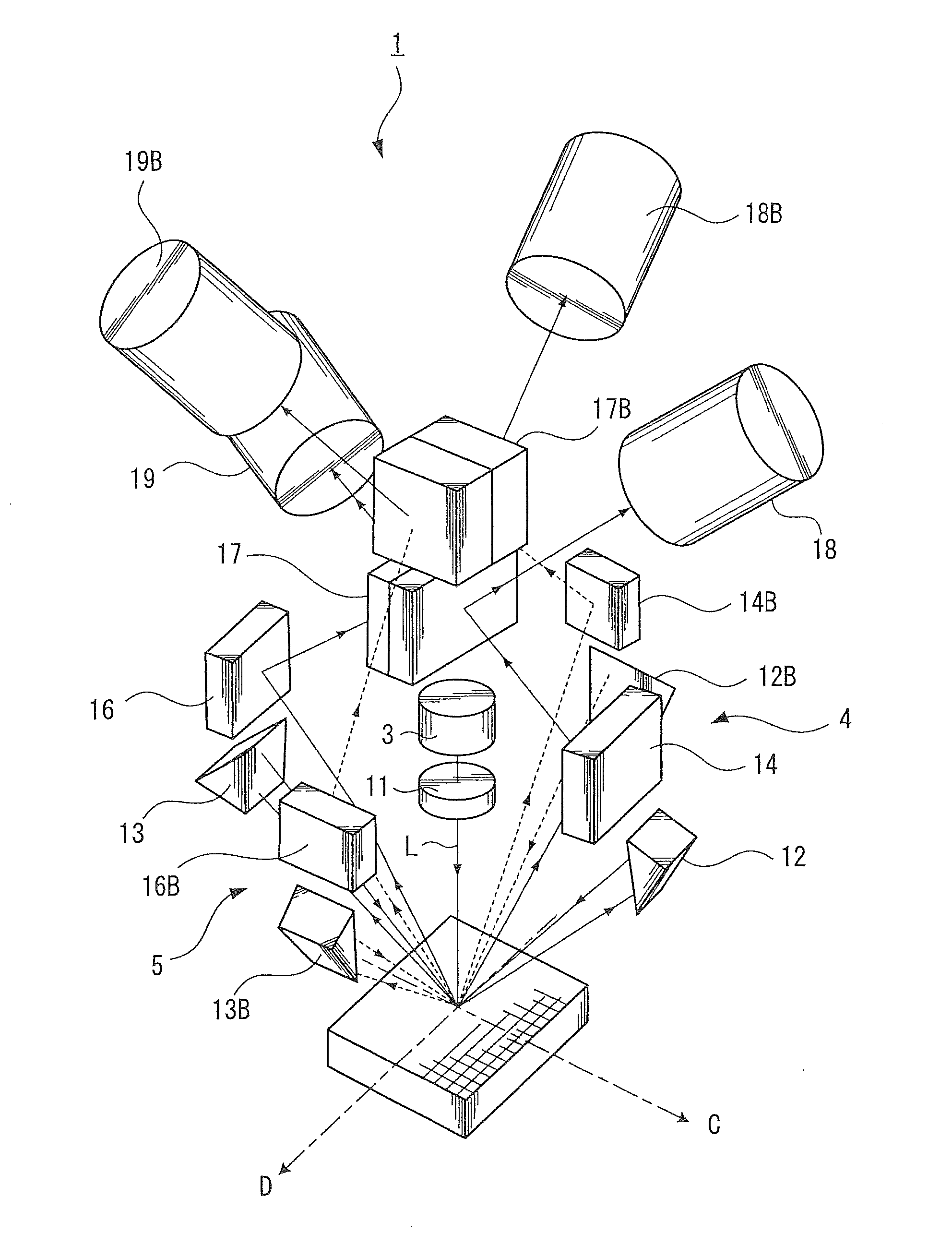
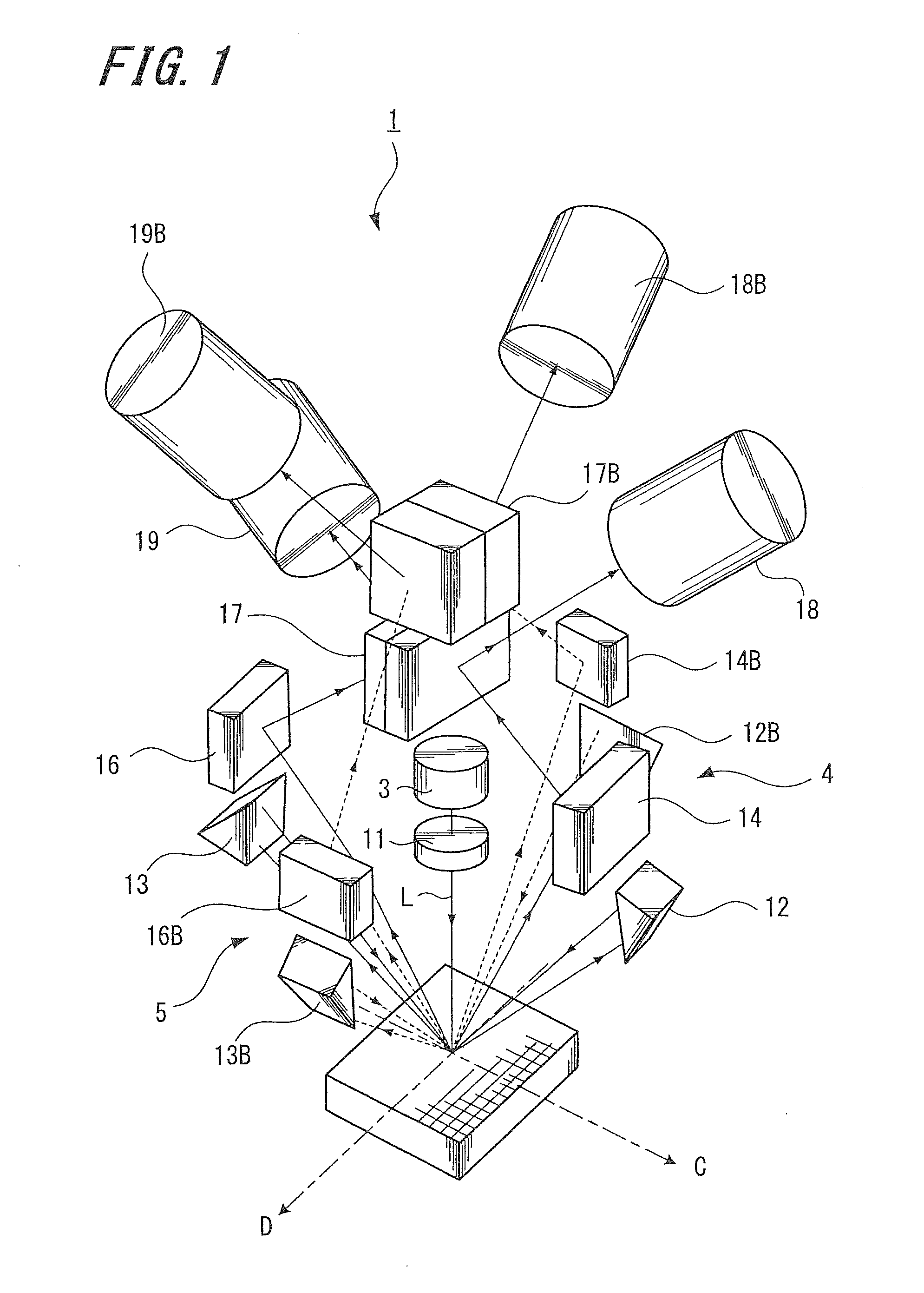
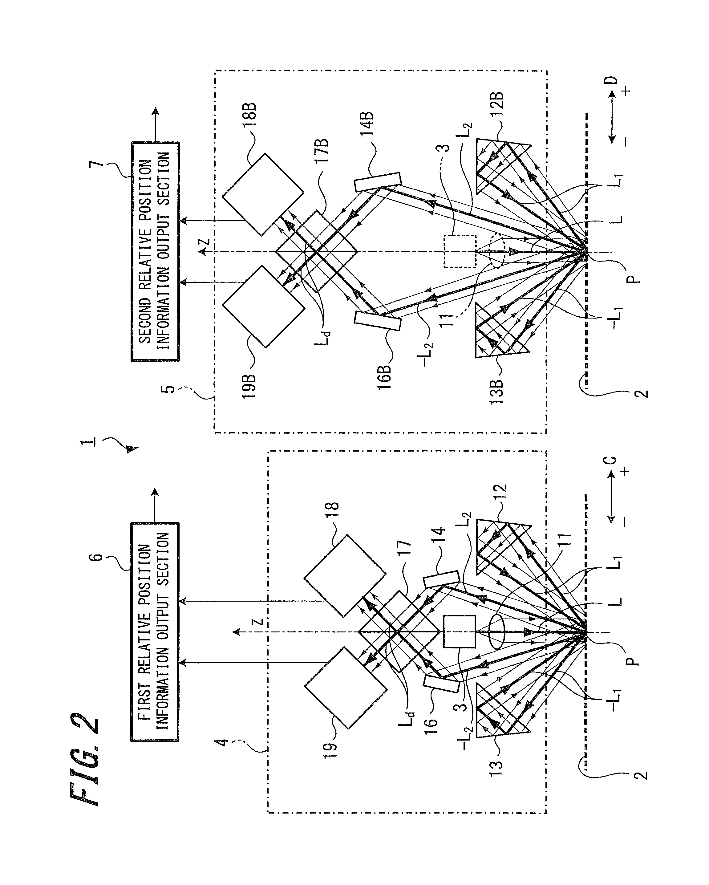
[0037]FIG. 1 is a perspective view showing an optical system of a displacement detecting device 1 according to the present embodiment, and FIG. 2 is a side view showing an optical system of the displacement detecting device 1.

[0038]The displacement detecting device 1 according to the present embodiment is a displacement detecting device capable of detecting two-dimensional (i.e., planar) displacement using a reflective composite diffraction grating. As shown in FIGS. 1 and 2, the displacement detecting device 1 includes a first grating interferometer 4, a second grating interferometer 5, a first relative position information output section 6, and a second relative position informati...

second embodiment

2. Second Embodiment

[0081]Next, a displacement detecting device 31 according to a second embodiment of the present invention will be described below with reference to FIGS. 7 and 8.

[0082]FIG. 7 is a side view showing an optical system of the displacement detecting device 31 according to the second embodiment, and FIG. 8 is a block diagram showing a relative position information output section of the displacement detecting device 31.

[0083]The displacement detecting device 31 according to the second embodiment differs from the displacement detecting device 1 of the first embodiment in that a lens is provided between the composite diffraction grating 2 and each reflector and that the configuration of both the first light receiving section and the second light receiving section is different, and therefore the description below will be focused on these differences. Thus, in the displacement detecting device 31 of the second embodiment, like components are denoted by like reference numera...

third embodiment

3. Third Embodiment

[0117]Next, a displacement detecting device 61 according to a third embodiment of the present invention will be described below with reference to FIGS. 9, 10A and 10B.

[0118]FIG. 9 is a side view showing an optical system of the displacement detecting device 61 according to the third embodiment of the present invention. FIGS. 10A and 10B are each an enlarged view showing a primary portion of the displacement detecting device 31 according to the third embodiment of the present invention.

[0119]The displacement detecting device 61 of the third embodiment differs from the displacement detecting device 31 of the second embodiment in the configuration of the first lens and the second lens. Thus, in the displacement detecting device 61 of the third embodiment, like components are denoted by like reference numerals as of the displacement detecting device 31 of the second embodiment, and the explanation thereof will be omitted, so that description will focus on the first le...


PUM


Abstract

A displacement detecting device has a diffraction grating, grating interferometers, and relative position information output sections. The grating interferometers have a light source, reflectors, a beam splitter, and light receiving sections. The reflectors reflect 1st-order diffracted lights diffracted by the diffraction grating, and cause the reflected 1st-order diffracted lights to be incident at a position substantially identical to the position at which the light from the light source is irradiated. Furthermore, the reflectors cause the 1st-order diffracted lights to be incident on the diffraction grating at an angle different to either the incidence angle of the light from the light source incident on the diffraction grating or the angle at which the 1st-order diffracted lights are transmitted through or reflected by the diffraction grating.

Description

CROSS REFERENCES TO RELATED APPLICATIONS[0001]The present invention contains subject matter related to Japanese Patent Application JP 2010-140904 filed in the Japanese Patent Office on Jun. 21, 2010, the entire contents of which being incorporated herein by reference.BACKGROUND OF THE INVENTION[0002]1. Field of the Invention[0003]The present invention relates to a displacement detecting device which detects the amount of displacement (movement) of a diffraction grating (a scale) by using interference of light.[0004]2. Description of the Related Art[0005]Conventionally, displacement detecting devices having a scale and a detection head are widely used as measuring instruments for accurately measuring linear displacement, rotational displacement and the like. In recent years, displacement detecting devices using the light emitted from a light-emitting diode or laser are used. Further, there is a demand for high-resolution displacement detecting devices capable of measuring a displacem...

Claims


Application Information

Patent Timeline
IPC IPC(8): G01B9/02
CPCG01D5/38G01D2205/90
Inventor TAMIYA, HIDEAKI
Owner DMG MORI SEIKI CO LTD
Why Eureka
Try Eureka