
Method for manufacturing panels and panels obtained hereby

a technology of manufacturing panels and panels, applied in the direction of dye addition to spinning solution, light beam reproducing, instruments, etc., can solve the problems of no longer esthetically attractive, damaged decoration top layer, high production cost, etc., and achieve the effect of cost-effective manufacturing and better color rendition

Inactive Publication Date: 2011-12-22
FLOORING IND LTD
View PDF4 Cites 103 Cited by
  • Summary
  • Abstract
  • Description
  • Claims
  • Application Information

AI Technical Summary

Benefits of technology

The present invention offers an alternative method for manufacturing panels with colored sides, which is more economical and efficient than previous methods. The method involves adding a colorant to a material mass before or during the process of densifying the material. The colorant can be added in a continuous manner, and the density of the material mass is at least doubled prior to achieving the final density. The colorant can be added prior to one or more press treatments, and the material mass is in a state of less than half of its final density after the addition of the colorant. The colorant can be added in a state of more than 90% of its final density. The colorant can be a liquid colorant or a pigment. The method allows for the formation of patterns and motifs with a high resolution. The use of multiple colorants can offer more flexibility in terms of coloration options.

Problems solved by technology

However, the disadvantage of a laminate floor panel is that with wear traces of minor depth, the decor-forming top layer already is damaged such that it is no longer esthetically attractive.
Such floor panel and production procedure are expensive.
Moreover, in such floor panels no patterns or motifs can be formed by means of the color pigments, or anyway the possibilities therefor certainly are limited.
Generally, it is known that staining agents can penetrate into the substrate over a very limited depth only and that it is difficult to obtain a good color rendition at the surface of the substrate.

Method used


Image

  • Method for manufacturing panels and panels obtained hereby
  • Method for manufacturing panels and panels obtained hereby
  • Method for manufacturing panels and panels obtained hereby

Examples


Embodiment Construction

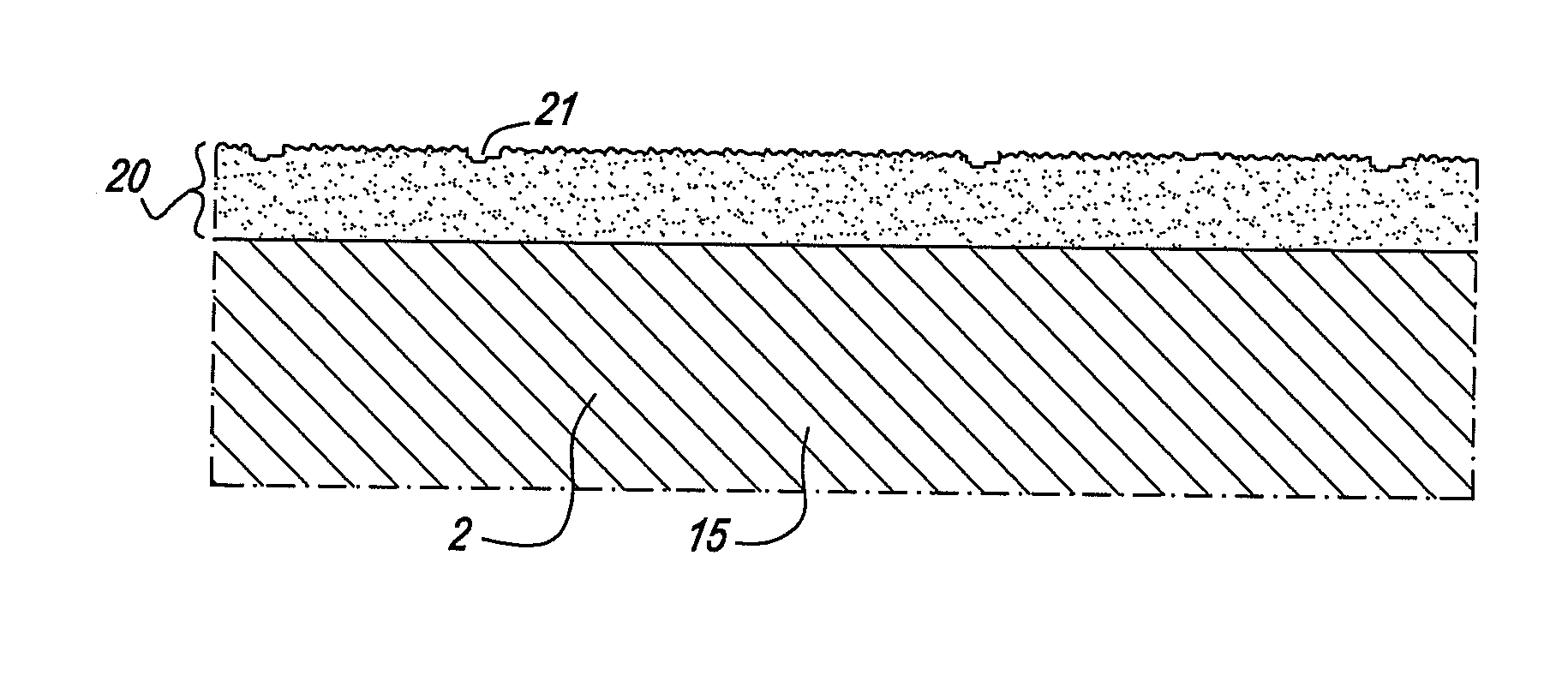
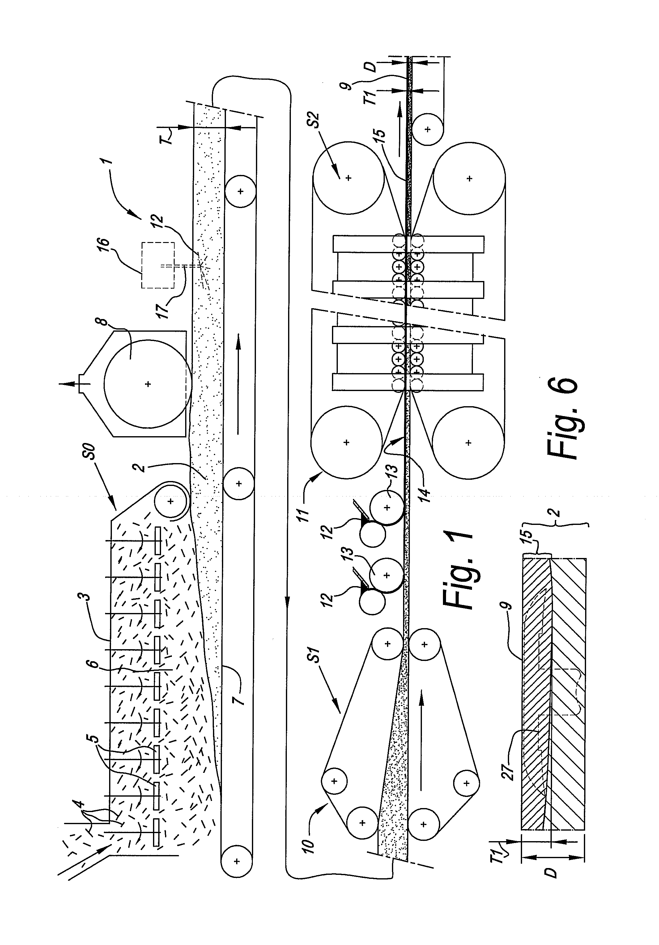
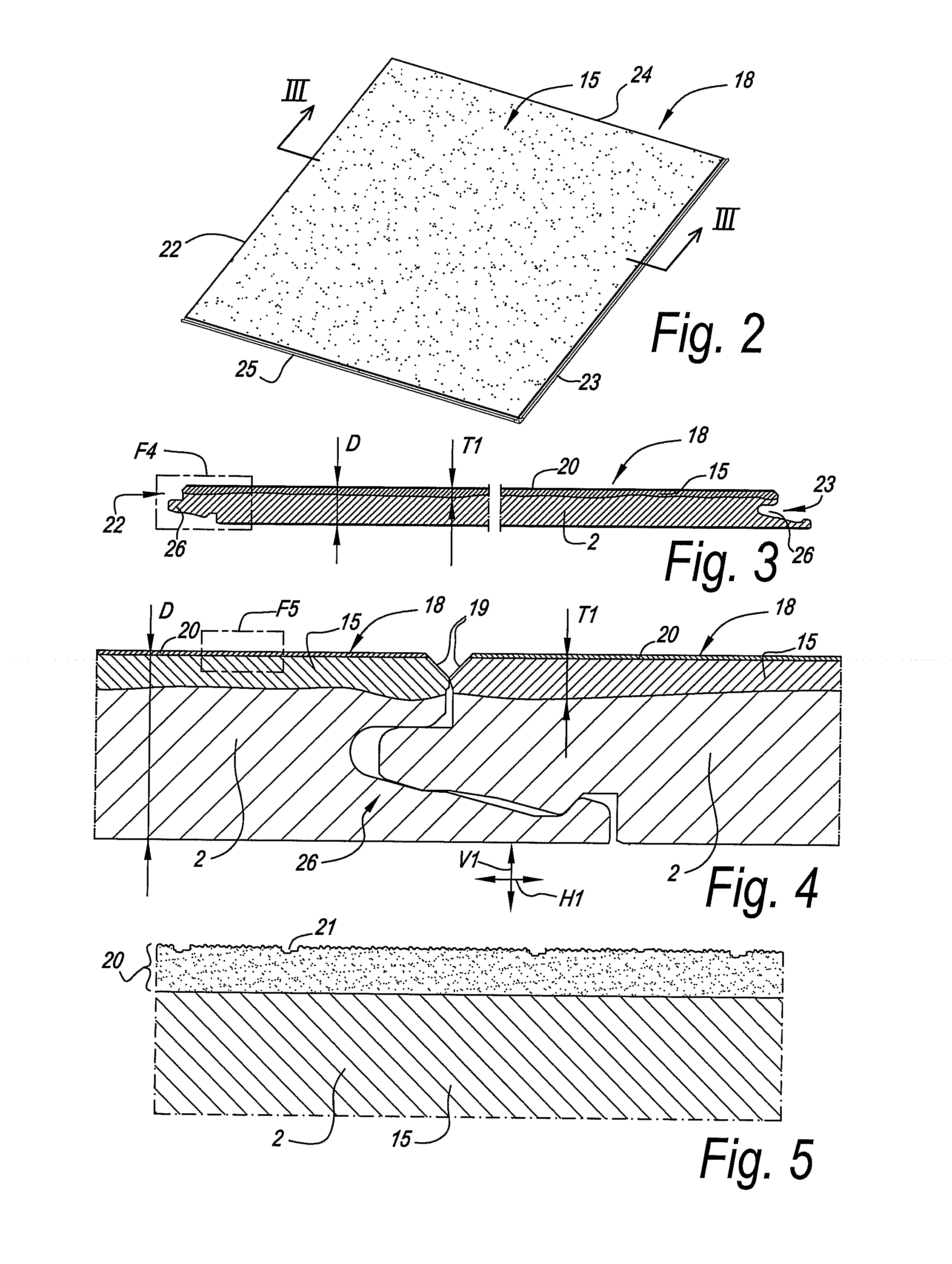
FIG. 1 schematically represents some steps S0-S1-S2 in a method having the characteristics of the first aspect of the invention. In the example, this relates to a method which is performed by means of a production line 1, which substantially corresponds to a typical MDF or HDF production line. Herein, it is started from a material mass 2, which, in a preceding step S0, has been composed at least by means of two components. In this case, both components together are supplied to a strewing machine 3, in the form of wood particles previously provided with binding agent, more particularly wood fibers 4 provided with polycondensation glue.

The strewing machine 3 of such production line 1 may be constructed in any manner. In the example, a strewing machine 3 is applied such as the one known from WO 03 / 053642. The strewing machine 3 of the example is provided with a plurality of agitating elements 5, which put the wood fibers 4, which are provided with glue, in motion in the strewing chambe...


PUM

PropertyMeasurementUnit
thicknessaaaaaaaaaa
depthaaaaaaaaaa
thicknessesaaaaaaaaaa

Abstract

A method for manufacturing panels including a substrate on the basis of a pressed material mass, whereby it is started from a material mass to be densified, wherein the density of this material mass, in one or more densifying steps, is at least doubled. Prior to one or more of these densifying steps, a colorant is added to the material mass.

Description

BACKGROUND OF THE INVENTION1. Field of the InventionThis invention relates to a method for manufacturing panels and to panels obtained hereby.More particularly, the invention relates to panels comprising a substrate, wherein this substrate substantially consists of a pressed material mass.2. Related ArtSuch panels are known as such. The substrates applied herein may consist, for example, of wood particle board or wood fiberboard, such as MDF or HDF (Medium Density Fiberboard or High Density Fiberboard). According to the state of the art, such panels, at least at one flat side thereof, can be finished with a top layer forming a separate decor. For example, from WO 97 / 47834 laminate floor panels are known, wherein MDF or HDF (Medium Density Fiberboard or High Density Fiberboard) is applied for the substrate and wherein one or more paper layers provided on this substrate are applied for the top layer. One of said paper layers then is provided with a print, for example, with a wood moti...

Claims


Application Information

Patent Timeline
Patent Type & Authority Applications(United States)
IPC IPC(8): B32B3/00B29C43/20
CPCB27N3/08Y10T428/26B27N7/005B27N3/18
Inventor MEERSSEMAN, LAURENTVANHASTEL, LUC
Owner FLOORING IND LTD
Learn More