Vascular clamp structure

a vascular clamp and clamping technology, applied in the field of vascular clamps, can solve the problems of difficult separation of two leg parts, occurrence of slippage phenomenon, etc., and achieve the effect of improving the structure enhancing the clipping force and increasing the friction area between the inter-contacting parts of the vascular clamp

Inactive Publication Date: 2011-12-22
TOP BOUND ENTERPRISE +1
View PDF6 Cites 162 Cited by
  • Summary
  • Abstract
  • Description
  • Claims
  • Application Information

AI Technical Summary

Benefits of technology

[0007]The main objective of the present invention is to provide an improved vascular clamp structure. Two ends of the vascular clamp are respectively equipped with a clipping piece, whereby the friction area between the inter-contacting parts of the vascular clamp can be increased. At adjacent faces between two clipping pieces, there is a set of male and female fasteners inter-assembled to each other, effectively enhancing the clipping force of the vascular clamp, and improving the drawback of easy slippage of traditional vascular clamps.

Problems solved by technology

This kind of design results in small contacting area between the two leg parts of the clamp and the vessel, causing an occurrence of slipping phenomenon, due to insufficient friction exerting between the vascular clamp and vessel.
Furthermore, it is difficult to separate the two leg parts after the hemostat of a traditional single clip body has clamped something.

Method used


Image

  • Vascular clamp structure
  • Vascular clamp structure
  • Vascular clamp structure

Examples


Embodiment Construction

[0032]In cooperation with attached drawings, the technical contents and detailed description of the present invention are described thereinafter according to a number of preferable embodiments, not used to limit its executing scope. Any equivalent variation and modification made according to appended claims is all covered by the claims claimed by the present invention.

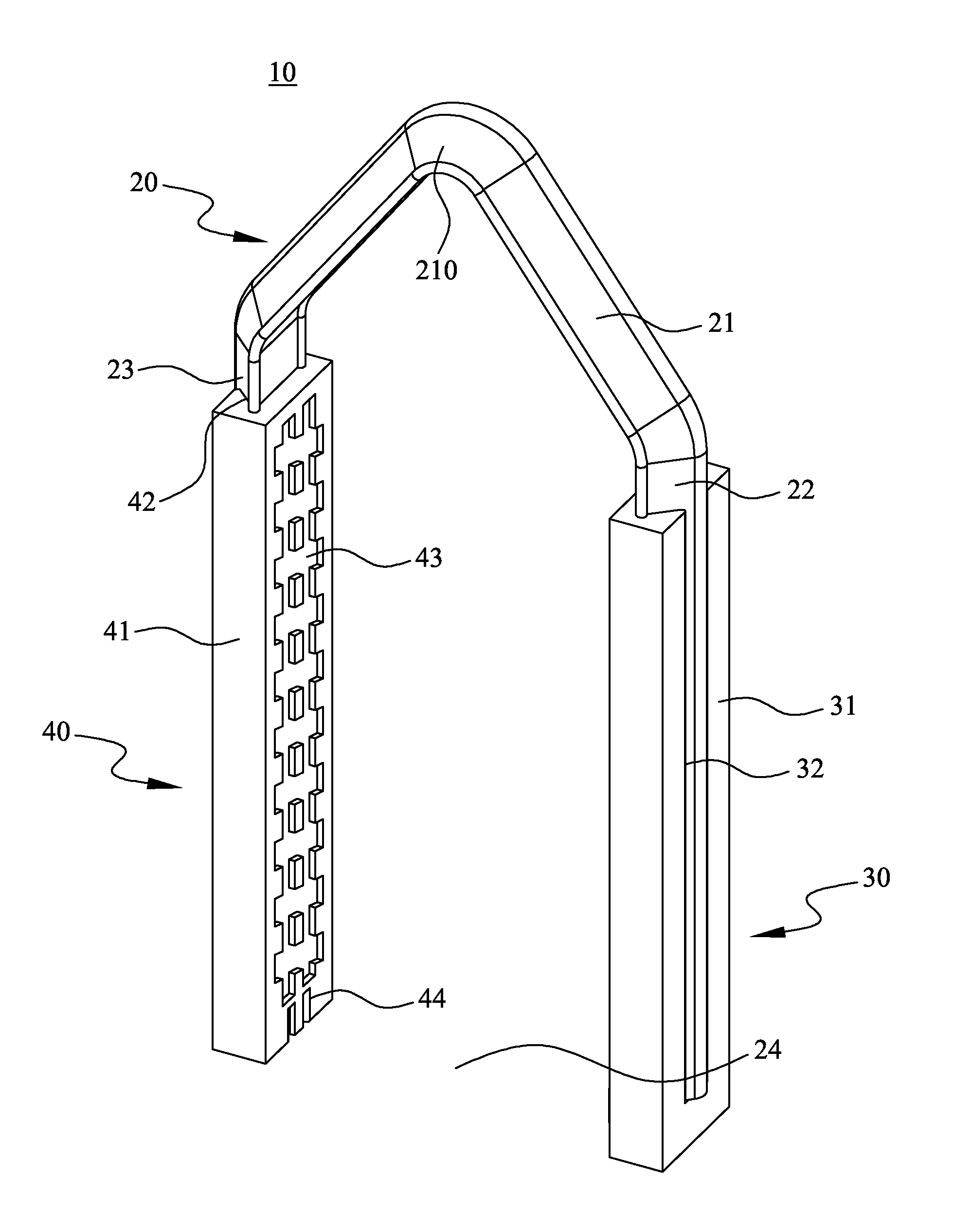
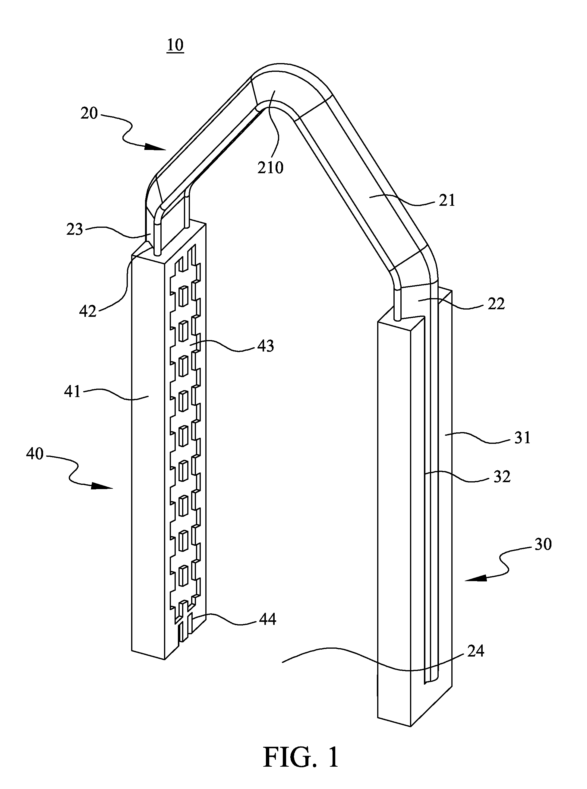
[0033]First of all, please refer to FIG. 1 and FIG. 10 to FIG. 12. As shown in these figures, the vascular clamp 10 of the invention is comprised of a clip body 20, a first clipping piece 30 connected to one end of the clip body 20 and a second clipping piece 40 connected to another end of the clip body 20. During an operation, the vascular clamp 10 is matched with the medical clamping plier 50 and suppressed to deform to ligate a vessel.

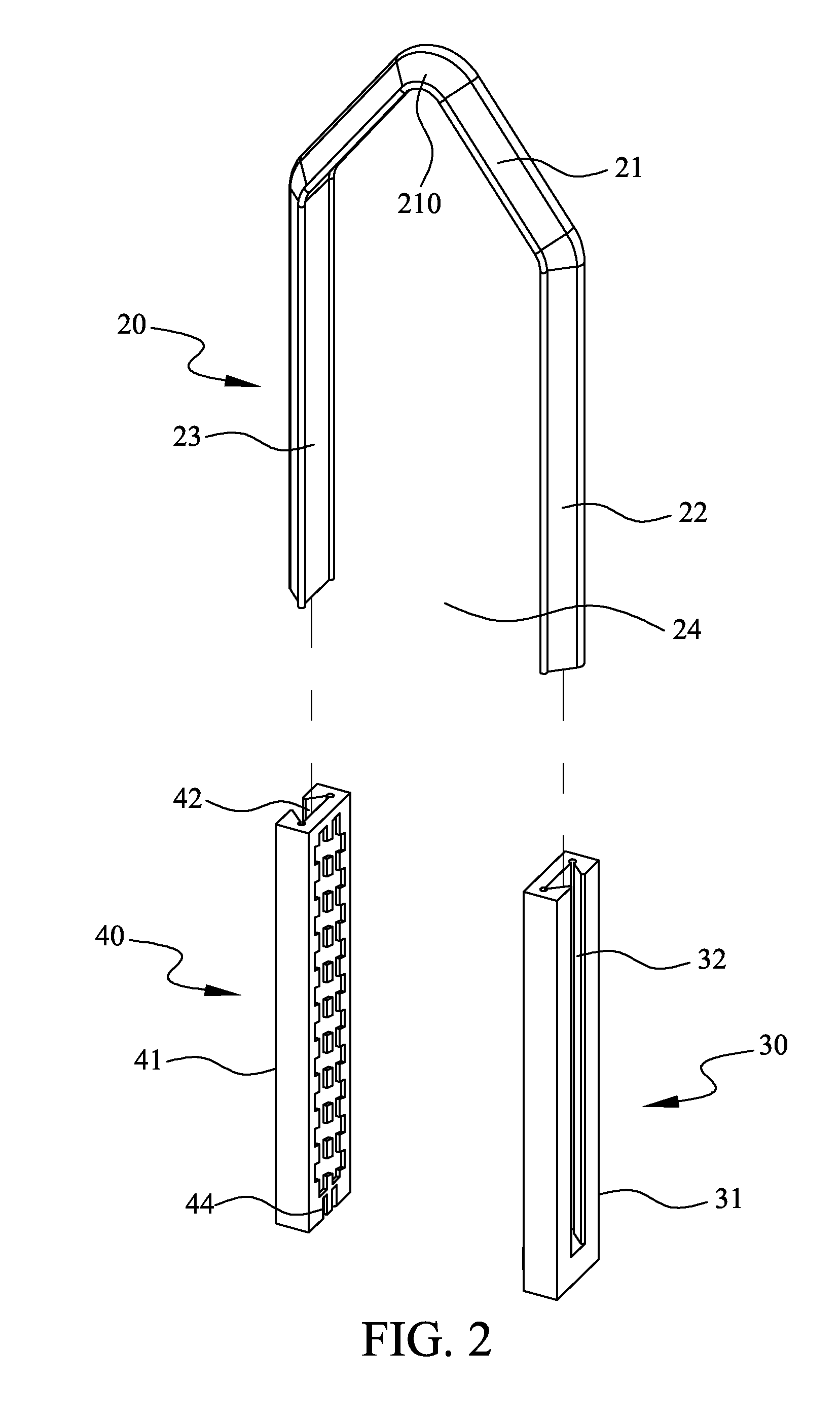
[0034]Secondly, please refer to FIG. 2. As shown in this figure, the clip body 20 of the vascular clamp 10 is arranged with a bridge part 21. The bridge part 21 is configured as a V-sh...


PUM


Abstract

An improved vascular clamp structure is comprised of a clip body and two clipping pieces, all of which constitute a vascular clamp used cooperatively for medical clamping pliers. The clip body is arranged with a bridge part, and from two ends of which a clipping part extends respectively and making one side of the clip body forming an opening; the clipping piece is arranged with a clipping body with a fitting slot. The fitting slot and the clipping part can be assembled together. Both adjacent faces of the clipping bodies are respectively arranged with a groove and at least one male or female fastener inter-buckled together. Wherein, the clip body is set as a memory metal. By arranging clipping pieces, the vascular clamp of the present invention enhances the frictional areas of inter-contact. Arranging male and female fasteners at the adjacent faces of clipping pieces also enhances the clipping force, and effectively improves the slipping drawback of traditional vascular clamp. In addition, the vascular clamp is made of memory metal; by the separation of male and female fasteners, the vascular clamp further possesses the function of dismantlement.

Description

FIELD OF THE INVENTION[0001]The present invention in general relates to a vascular clamp cooperatively used for medical pliers, in particular, to an improved vascular clamp structure with a clip body, two ends of which have clipping pieces capable of clipping enhancement.DESCRIPTION OF PRIOR ARTBACKGROUND OF THE INVENTION[0002]In general surgery medical operation, it needs to incise or ligate blood vessels within an organ or tissue. Since organs and tissues of human bodies are not completely identical, and each person's individual constitutions are not all the same, so vascular ligations required in surgery are also different.[0003]General vascular ligation methods are divided into three types: the first method is to carry suture ligation to the wall of blood vessels; the second one is to carry electric sintering ligation on the vascular wall with laser, high frequency electric knife or other plasma of high amount of energy; and, the last method is to use a medical clamp to clamp th...

Claims


Application Information

Patent Timeline
Patent Type & Authority Applications(United States)
IPC IPC(8): A61B17/12
CPCA61B17/0643A61B17/122A61B2017/00867A61B2017/00433A61B2017/00858A61B17/1285
Inventor YEH, YEN-MING
Owner TOP BOUND ENTERPRISE
Why Eureka
Try Eureka