Circuit constant analysis method and circuit simulation method of equivalent circuit model of multilayer chip inductor
a technology of equivalent circuit model and circuit constant analysis, which is applied in the direction of electric/magnetic computing, instruments, analogue processes for specific applications, etc., can solve the problems of significant errors, circuit configuration becomes considerably complicated, and the order of polynomial needs to be increased, so as to achieve the effect of suppressing the performance of an actual circui
- Summary
- Abstract
- Description
- Claims
- Application Information
AI Technical Summary
Benefits of technology
Problems solved by technology
Method used
Image
Examples
embodiment 1
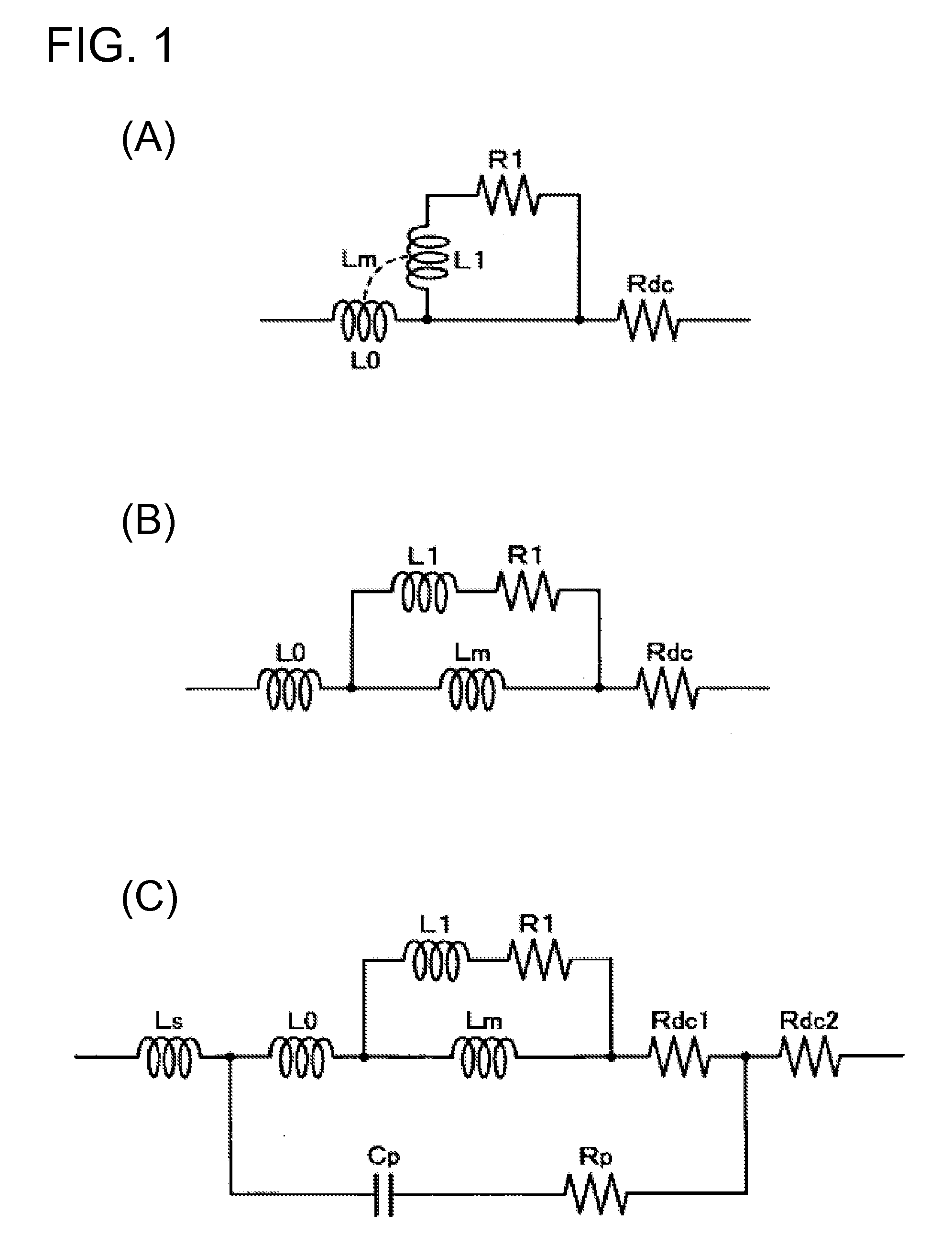
[0026]First, in order to facilitate understanding of the present invention, how an equivalent circuit of the present invention is brought about from the ladder circuit described above is described with reference to FIG. 1. As shown in FIG. 6(B), in the ladder circuit of Cao et al., the direct current resistance is not the direct current resistance Rdc of the conductor originally defined, rather it is a parallel circuit of Rdc and R1. Thus, as shown in FIG. 1(A), in the present invention, a series circuit of an inductance L1 and a resistance R1 for taking the skin effect of the conductor into consideration is shorted with respect to direct current, and then connected in series to an inductance L0 with respective to the direct current and to a direct current resistance Rdc of the conductor.
[0027]Next, if a mutual inductance Lm between the inductances L0 and L1, which is included in the improved ladder circuit of FIG. 1(A), is expressed in a decoupling form, then it becomes the circuit...
embodiment 2
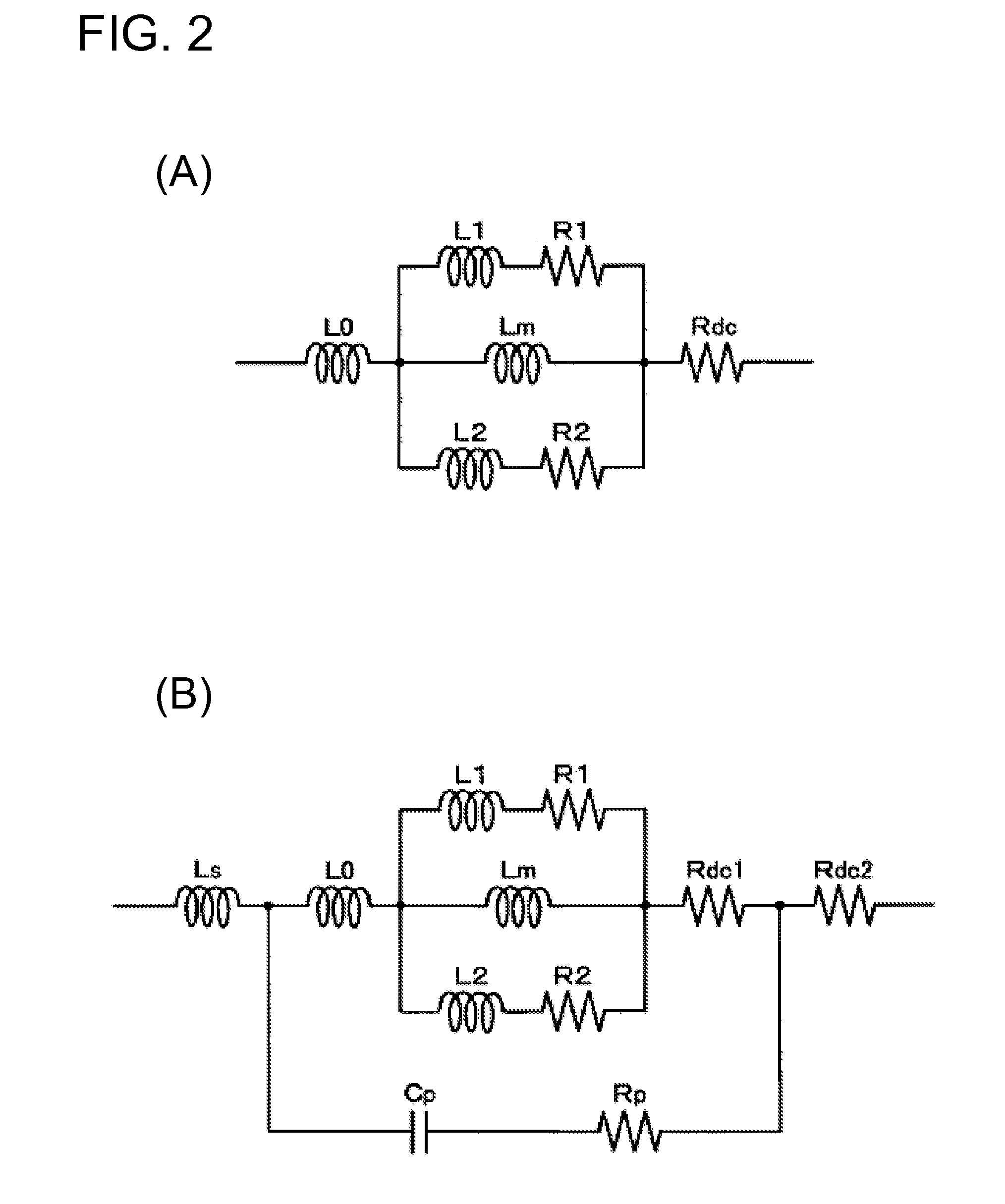
[0034]Next, Embodiment 2 of the present invention is described with reference to FIG. 2. In the ladder circuit in the decoupling form shown in FIG. 1(B), if the thickness of a metal layer constituting the internal conductor of the multilayer chip inductor is taken into consideration, it becomes an equivalent circuit shown in FIG. 2(A). That is, the skin effect of side surfaces of the metal layer is expressed as a series circuit of an inductance L2 and a resistance R2, and this is connected in parallel to the series circuit of the inductance L1 and the resistance R1, which takes into consideration the skin effect of both upper and lower main surfaces of the metal layer, and to the inductance Lm expressed in the decoupling form.
[0035]Next, in a manner similar to the previous Embodiment, an equivalent circuit of the present embodiment shown in FIG. 2(B) is obtained by taking into consideration the dielectric loss and a parasitic inductance and resistance of the external electrode at th...
specific example
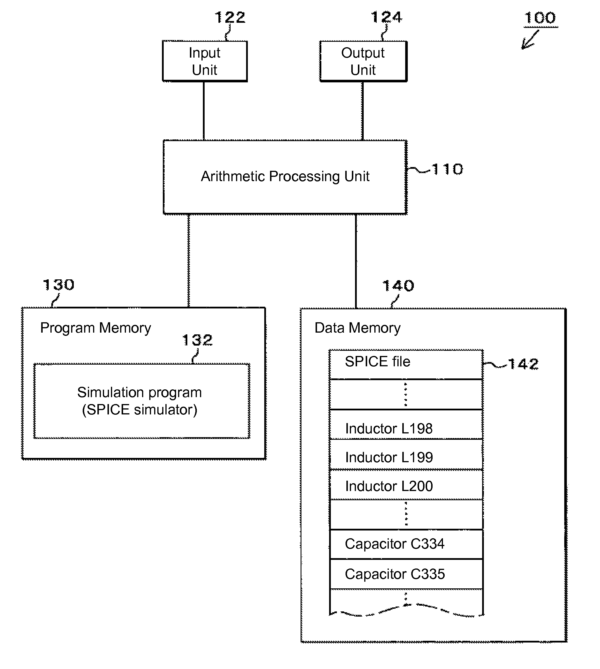
[0037]Next, referring to FIG. 3 to FIG. 4, examples of specific numerical values of the Embodiments and simulation examples of the Embodiments are described below. In order to perform a simulation using the equivalent circuit model of the Embodiments as described above, it is necessary to specifically determine circuit constants included in each of the equivalent circuits. For example, when using a multilayer chip inductor manufactured by “ABC” corporation having the model No. “000,” values of the circuit constants for this component needs to be determined specifically. To do this, a variety of methods such as Newton's method and the like are known. For an example, a technique based on a global optimization algorithm is described below. First,
Z_test(fn)=ESR_test(fn)+jX_test(fn)
is taken to be an actual measured value of the impedance at a frequency fn of the particular subject component. Also,
Z_circuit(V,fn)=ESR_circuit(V,fn)+jX_circuit(V,fn)
is taken to be a circuit impedance at the ...
PUM
 Abstract
Description
Claims
Application Information
 - R&D
- Intellectual Property
- Life Sciences
- Materials
- Tech Scout
- Unparalleled Data Quality
- Higher Quality Content
- 60% Fewer Hallucinations
Browse by: Latest US Patents, China's latest patents, Technical Efficacy Thesaurus, Application Domain, Technology Topic, Popular Technical Reports.
© 2025 PatSnap. All rights reserved.Legal|Privacy policy|Modern Slavery Act Transparency Statement|Sitemap|About US| Contact US: help@patsnap.com


