Eureka AIR delivers breakthrough ideas for toughest innovation challenges, trusted by R&D personnel around the world.

Exposure apparatus and device manufacturing method

a technology of exposure apparatus and manufacturing method, which is applied in the direction of photomechanical treatment, printing, instruments, etc., can solve the problems of change in degassing capability, limit in degassing capability, etc., and achieve the effect of preventing the occurrence of micro-bubbles and deterioration of optical performan

Inactive Publication Date: 2011-07-12
CANON KK
View PDF29 Cites 0 Cited by
  • Summary
  • Abstract
  • Description
  • Claims
  • Application Information

AI Technical Summary

Benefits of technology

[0023]The present invention has been made in consideration of the above-described problem, and attains a liquid immersion exposure technique that eliminates affects of the atmospheric pressure and fluctuations in dissolved gas amount from factory equipment, thereby preventing occurrences of micro-bubbles and deterioration of optical performance.
[0026]According to the present invention, fluctuations in the amount of dissolved oxygen can be reduced by suppressing changes in degassing performance caused by changes in temperature, pressure and atmospheric pressure. As a result, changes in optical performance and refractive index of the immersion liquid, which are related to the amount of dissolved oxygen, can be suppressed. Further, an occurrence of micro-bubbles can be suppressed, and optical performance from deterioration can be prevented.

Problems solved by technology

On the other hand, there is a limit in the degassing capability, due to limitations in pressure resistance and space.
Thus, a change of the atmospheric pressure may cause changes in degassing capabilities.
Thus, changes in the amount of dissolved gases in the liquid immersion exposure apparatus may occur when there is a change in the atmospheric pressure or in the amount of dissolved gases in the immersion liquid supplied from the factory equipment, which may cause an occurrence of micro-bubbles and deterioration of the optical performance.

Method used


Image

  • Exposure apparatus and device manufacturing method
  • Exposure apparatus and device manufacturing method
  • Exposure apparatus and device manufacturing method

Examples


first embodiment

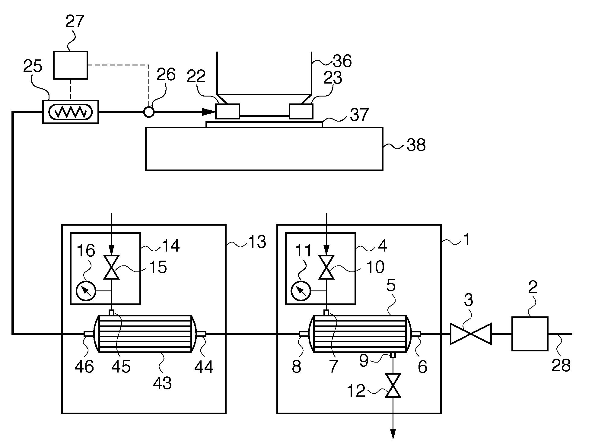
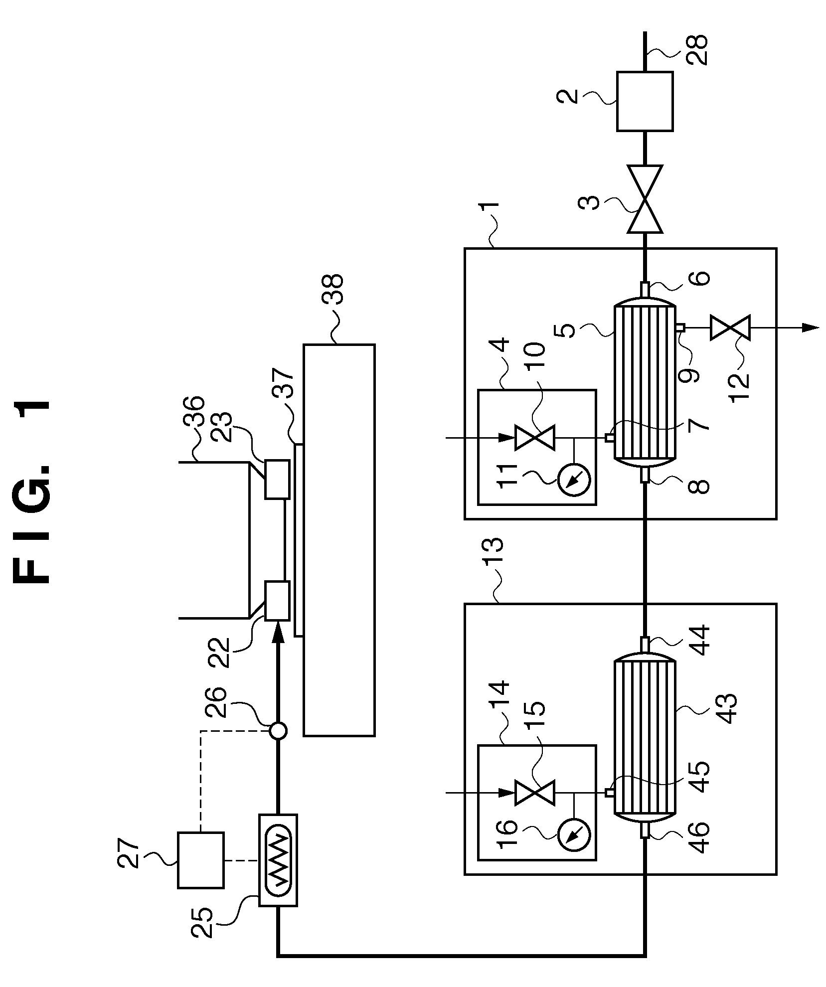
[0035]FIG. 1 shows the structure of an immersion liquid supply system of a liquid immersion exposure apparatus in the first embodiment of the present invention, and the same reference numerals used in FIG. 1 denote parts common to those in FIG. 4.

[0036]The immersion liquid supplied from the factory equipment passes through a supply line 28 and is supplied to a front side degassing unit 1. The temperature and flow rate of the immersion liquid are to be adjusted, and thus, it is desirable to set the front side degassing unit 1 downstream of a temperature adjustment 2 and a flow rate control unit 3. According to the structure, the fluctuation in degassing caused by the change of the pressure and temperature of the supplied immersion liquid can be eliminated, and further stability in degassing performance can be attained.

[0037]The front side degassing unit 1 has a degassing module 5 of which tube-shaped hollow fiber membranes are bundled together and have a structure in which a space is...

second embodiment

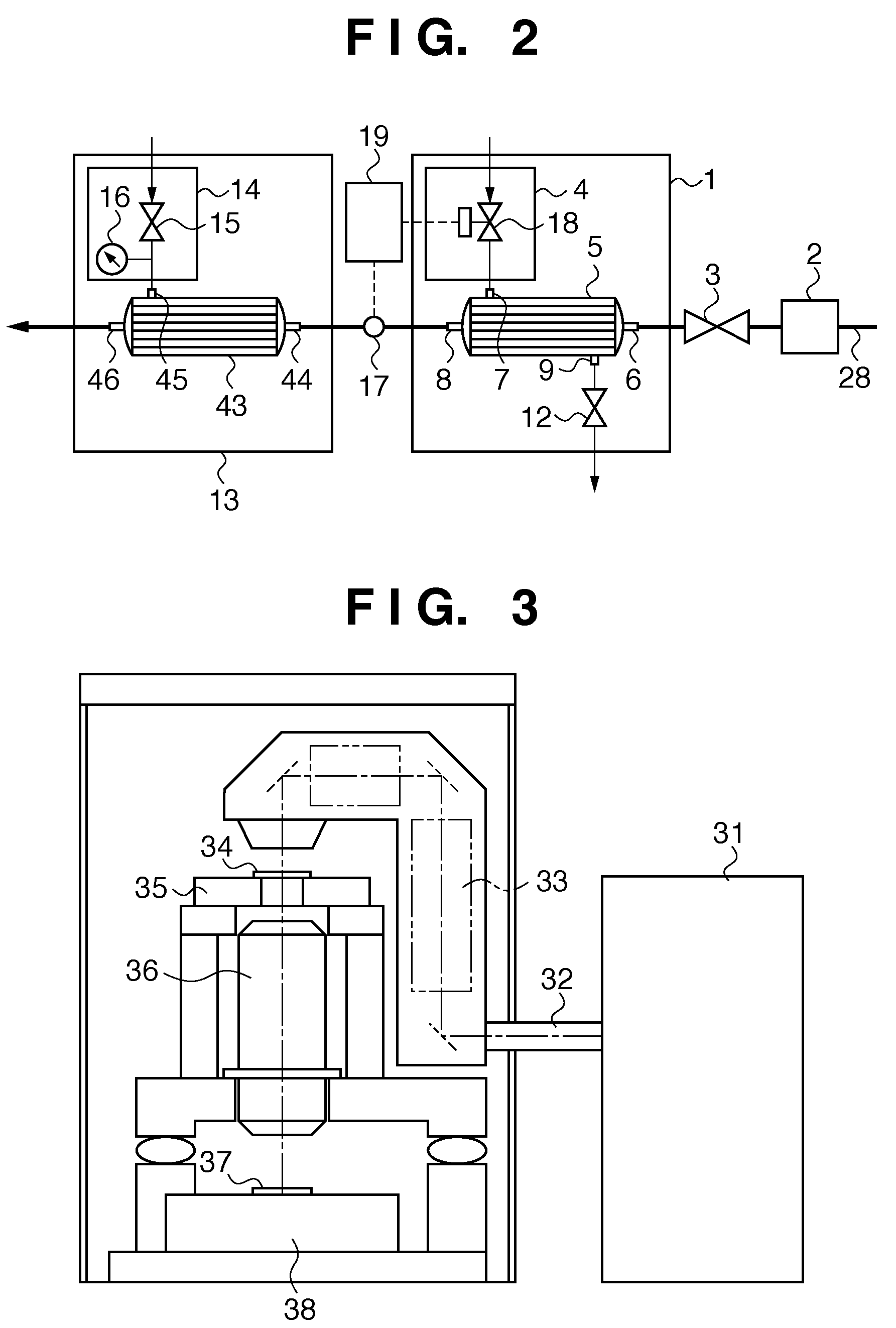
[0045]FIG. 2 shows the structure of a degassing unit of a liquid immersion exposure apparatus in a second embodiment of the present invention, and the same reference numerals as those in FIG. 2 denote parts common to the aforementioned first embodiment.

[0046]The present embodiment provides, between the front side degassing unit 1 and the rear side degassing unit 13 (in other words, downstream of the front side degassing unit 1 and upstream of the rear side degassing unit 13) a dissolved oxygen measurement sensor 17, which detects the amount of dissolved oxygen in the liquid immersion fluid.

[0047]Further, a nitrogen gas supply pressure control valve 18, which controls pressure by the amount of supplied nitrogen gas, is provided, and a dissolved oxygen control 19, which controls the nitrogen gas supply pressure control valve 18, such that the amount of dissolved oxygen detected by the dissolved oxygen measurement sensor 17 is constantly at a predetermined value, is provided.

[0048]The ...


PUM


Abstract

An exposure apparatus which exposes a pattern of an original onto a substrate via a projection optical system in a state in which a gap between the projection optical system and the substrate is filled with a liquid. A liquid supply unit supplies liquid to the gap. A front side degassing unit performs a degassing to the liquid prior to being supplied to the gap. A dissolved gas measurement unit is provided on the downstream side of the front side degassing unit, and a rear side degassing unit is provided on the downstream side of the dissolved gas measuring unit. The front side degassing unit has a dissolved oxygen control unit, which controls a supply amount of nitrogen gas so as to be the amount of dissolved oxygen, measured by the dissolved gas measurement unit, to a predetermined value.

Description

[0001]This application claims the benefit of Japanese Patent Application No. 2007-173110, filed Jun. 29, 2007, which is hereby incorporated by reference herein in its entirety.BACKGROUND OF THE INVENTION[0002]1. Field of the Invention[0003]The present invention relates to a liquid immersion exposure technique, which projects a pattern of an original onto a substrate in a stage in which a gap between the projection optical system and the substrate is filled with a liquid.[0004]2. Description of the Related Art[0005]FIG. 3 shows a general structure of an exposure apparatus.[0006]In FIG. 3, reference numeral 31 denotes a light source. In recent years, the light source 31 has shifted from an I-line to an excimer laser with a trend of shortening the wavelength due to miniaturization of exposure patterns, and even the laser source is shifted from KrF to ArF. Currently, in order to satisfy the demand of further miniaturization, the use of an F2 laser and EUV light are being investigated.[0...

Claims


Application Information

Patent Timeline
Patent Type & Authority Patents(United States)
IPC IPC(8): G03B27/42G03B27/52
CPCG03B27/42G03F7/70341G03F7/2041G03F7/70891
Inventor NOMOTO, MAKOTO
Owner CANON KK
Why Eureka
Eureka Blog
Learn More