Power supply detection circuitry and method

a detection circuit and power supply technology, applied in the field of data processing, can solve problems such as performance penalties, and achieve the effects of reducing the latency of powering up the processing circuit from the low leakage mode to the standby mode, simple design, and low overhead

Active Publication Date: 2011-12-22
ARM LTD
View PDF4 Cites 6 Cited by
  • Summary
  • Abstract
  • Description
  • Claims
  • Application Information

AI Technical Summary

Benefits of technology

[0014]The circuit of the present technique has a simple design and a low area overhead since the competition between the first transistor and the second transistor is sufficient to detect when the supply voltage level reaches the predetermined voltage level, and so few other timing controls are required in the circuit.
[0015]The processing circuit may be any logic circuit, such as a processor, memory or cache, or memory controller, for example. The predetermined voltage level may be any voltage level between the first voltage level and the second voltage level, but will typically be a voltage level that is closer to the second voltage level than the first voltage level. For example, the predetermined voltage level could be 95% of the way between the first voltage level and the second voltage level, such that the ready signal is output shortly before the supply voltage level reaches the second voltage level. In this way, the ready signal can provide the processing circuit with an early warning that the supply voltage level has almost reached the second voltage level. This enables the processing circuit, for example, to start performing a reset operation before the second voltage level has actually been reached, ready for actual processing to begin when the second voltage level has been reached. This enables the latency associated with powering up the processing circuit from the low leakage mode to the standby mode to be reduced.

Problems solved by technology

However, once the circuit has been placed in the low leakage mode, there will be a penalty in performance due to the time taken to switch the circuit back to the standby mode ready for the circuit to begin normal processing.

Method used


Image

  • Power supply detection circuitry and method
  • Power supply detection circuitry and method
  • Power supply detection circuitry and method

Examples


Embodiment Construction

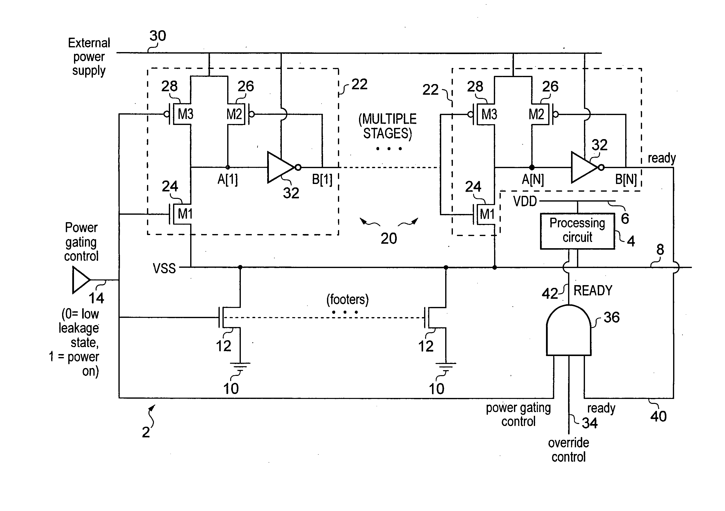
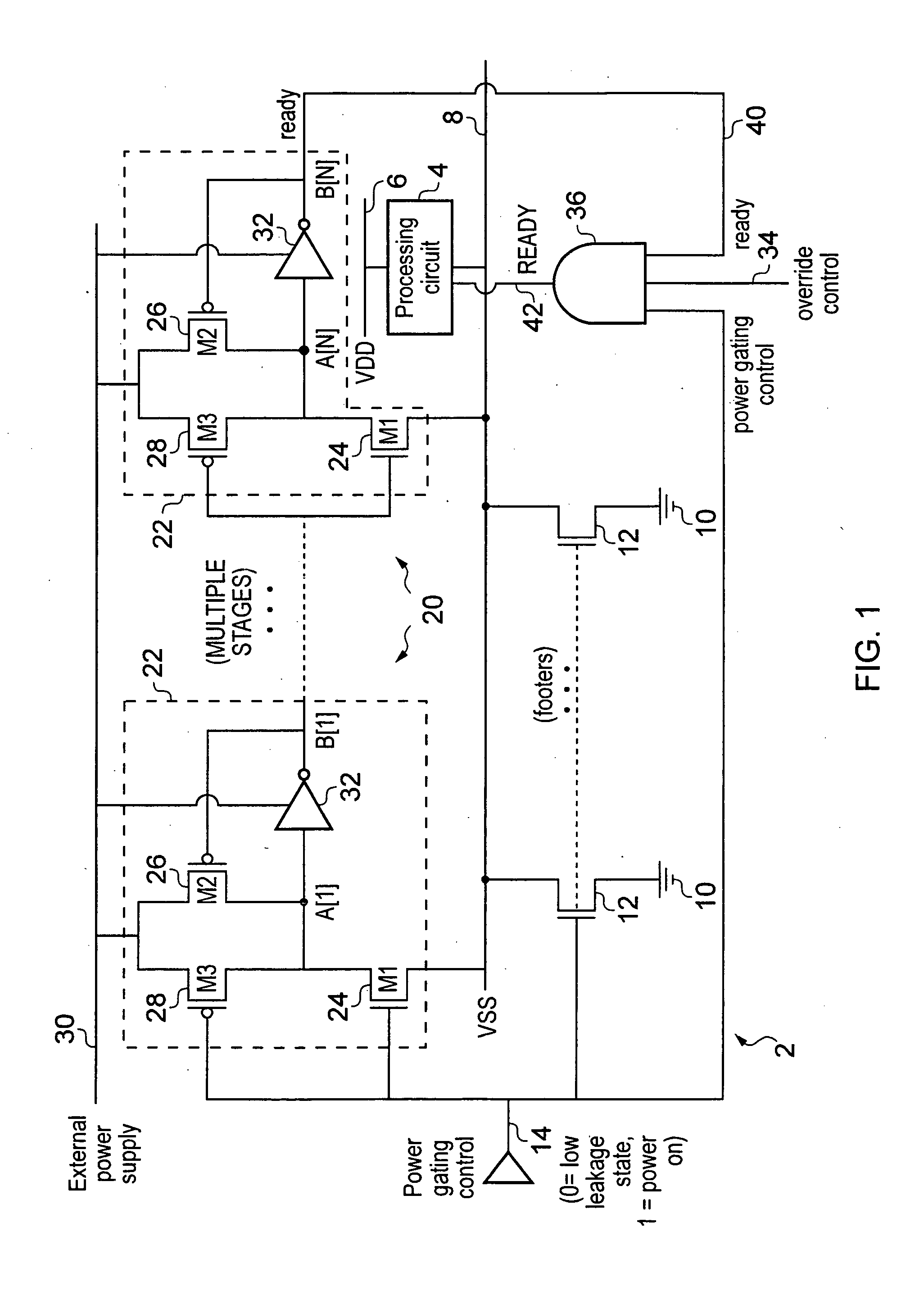
[0054]FIG. 1 illustrates a processing apparatus 2 having a processing circuit 4 coupled between VDD rail 6 and VSS rail 8. The processing circuit 4 may be any logic circuit such as a processor or a memory, for example. The VSS rail 8 is coupled to a ground supply 10 via footer circuits 12. While FIG. 1 illustrates two footer circuits 12, there may be more footer circuits. The footer circuits 12 are turned on and off in dependence on a power gating control signal 14. When the power gating control signal 14 has a high logic state then the footer switches 12 are turned on and the VSS line 8 is discharged to ground 10, so that the processing circuit 4 is in a standby mode ready for processing. When the power gating control signal 14 has a low logic level, then the processing circuit 4 is placed in a low leakage mode by switching the footer switches 12 off so as to allow the VSS rail 8 to float to a logic level higher than the ground level. In the low leakage mode, the voltage difference...


PUM


Abstract

When switching a power supply rail for a processing circuit from a first voltage level to a second voltage level, power level detection circuitry detects when the supply voltage level reaches a predetermined voltage level. The power level detection circuitry comprises a first transistor and a second transistor which compete with one another such that the first transistor pulls a signal node voltage level at a signal node towards the supply voltage level while the second transistor pulls the signal node voltage level towards an external power supply voltage level. When the supply voltage level on the power supply rail reaches the predetermined voltage level, the first transistor overcomes the second transistor to trigger a ready signal indicating that the supply voltage level has reached the predetermined voltage level.

Description

BACKGROUND OF THE INVENTION[0001]1. Field of the Invention[0002]The present invention relates to the field of data processing. More particularly, the invention relates to power supply detection circuitry for detecting when a supply voltage level has reached a predetermined voltage level.[0003]2. Background to the Invention[0004]In a data processing circuit, leakage current through the circuit contributes to the power consumed by the circuit, and so it may be desirable to reduce the amount of leakage current in order to reduce power consumption. One technique for reducing the leakage current is to gate the power supplied to the circuit block using power switches. The amount of leakage current is dependent on the voltage difference across the circuit. Hence, the processing circuit may be provided with a standby mode in which a given voltage difference is supplied to the circuit to enable processing operations to be performed, and a low leakage mode in which the voltage difference acro...

Claims


Application Information

Patent Timeline
Patent Type & Authority Applications(United States)
IPC IPC(8): G06F1/26H03K5/153
CPCH03K17/22H03K5/08
Inventor GAJJEWAR, HEMANGI UMAKANTYEUNG, GUS
Owner ARM LTD
Why Eureka
Try Eureka