Inherent in currently available measuring and analysis devices for pollutants or particles in a fluid, e.g. a gas, gas mixture or a liquid, and the corresponding measuring and analysis methods are a number of problems.
A first problem area involves particle separation.
This particle separation has been found to be difficult, in particular if the mixture involves microscopically small particulate matter.
The devices utilized here are relatively large and most often complicated and expensive to manufacture, which limits their use as wall or table devices.
In addition, particle sequestration in certain applications, and especially in sizes in the
micrometer range, is not good enough.
The problem lies here in the principle since a sequestration of particles for measurement is actually not necessary.
Disadvantages here are the additional necessary electrical parts and the
moisture sensitivity of this variant, which limits its application.
However, a
disadvantage of such filters is that they cause a pressure drop.
But a further and far more serious
disadvantage of these filters is that during operation they become progressively clogged by the retained particles.
In the event of danger, such a device would only inadequately be capable of detecting or they would detect nothing, e.g. the
fire detector would not indicate anything at all.
This requires regular filter exchanges since clogging of the filter, and therewith the blockage of the inflow into the measuring chamber, cannot be predicted.
A
disadvantage here is that the measuring chamber becomes polluted through
dirt deposits especially by larger particles, more electrical components are required and the setting and calibration of the device entails additional expenditures and effort.
If the optical measuring components take up particles during operation in progress, e.g. become dusty, their sensitivity is reduced.
However, there is a serious disadvantage of this drift compensation results, namely that the measuring behavior, and thereby also the response behavior, of the device, for example the
fire detector, changes in the course of operation and this change does not correlate with the actual sensitivity or the extent of
dirt deposits.
However, the design of this device is highly complex, especially since the aspiration mechanism is located within the duct and forms a part thereof.
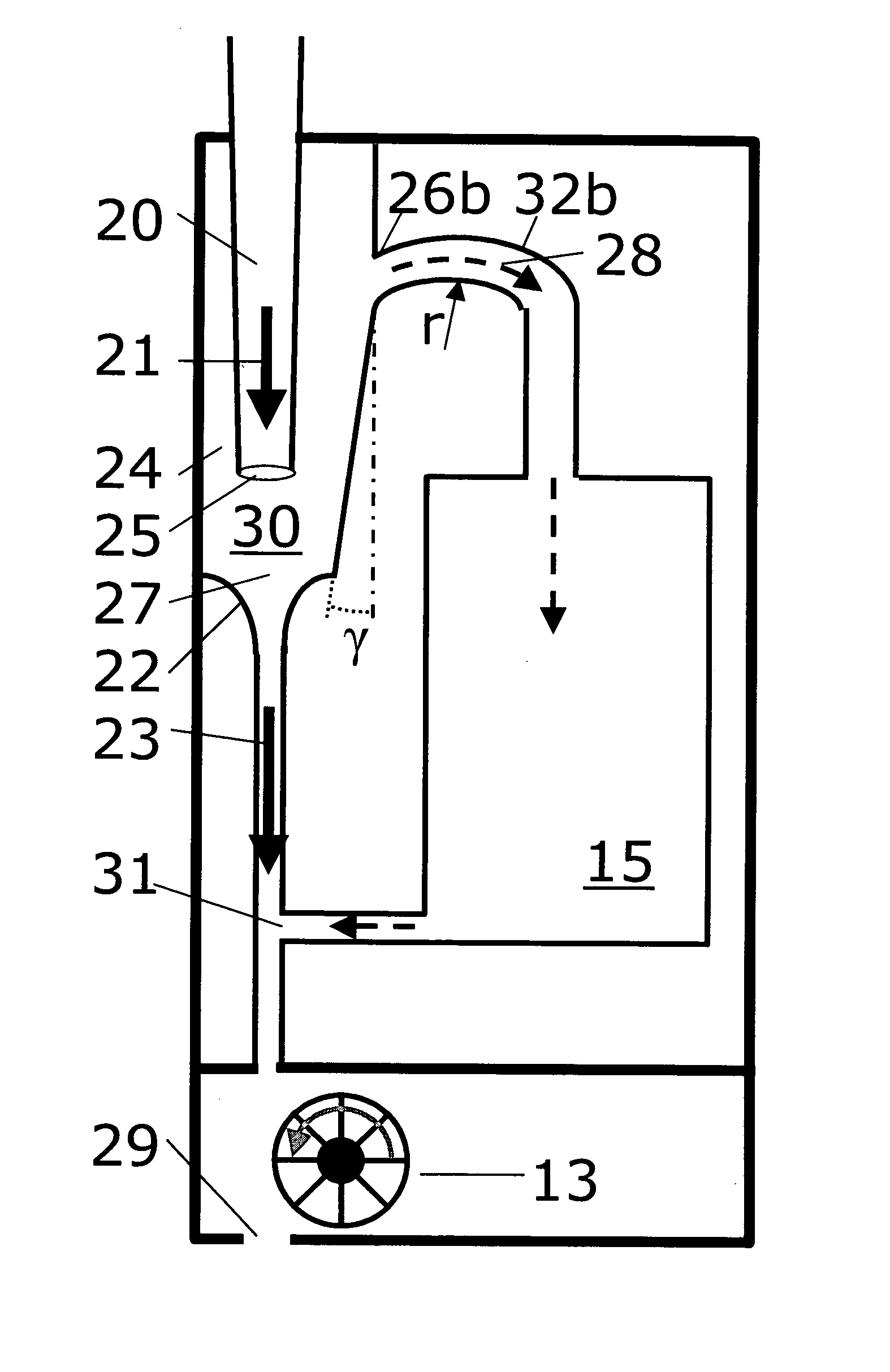
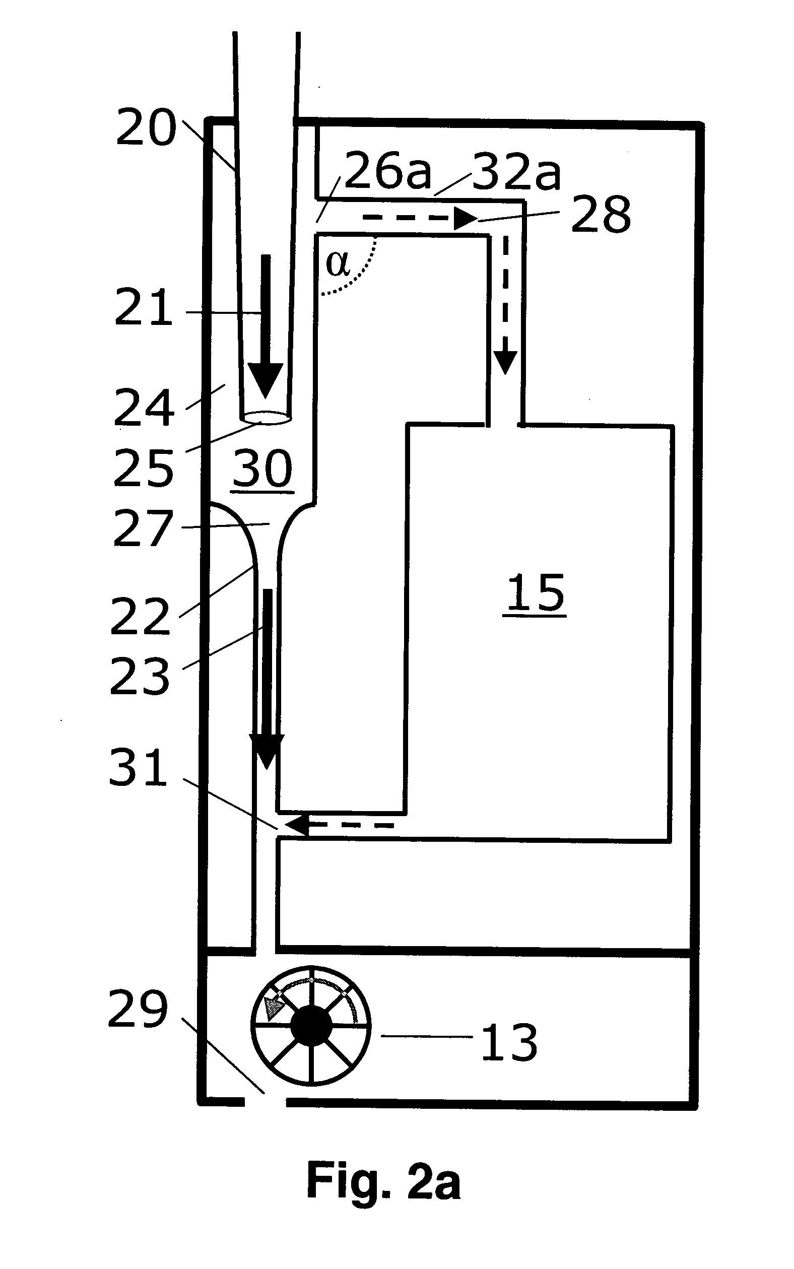
The second problem area relates to the accumulation of particulate matter in the measuring chamber, in particular on the optical or electronic components used for the measurement.
These result in turbulences of the flowing medium which, in turn, leads to accumulations of particulate matter, most often at undesirable sites.
This alone already distorts the measurement.
The extent of
dirt deposits and clogging cannot be determined, and consequently also not the time when the filter becomes clogged, resulting in the gas / air inflow into the measuring chamber being reduced or blocked.
A third problem area in the measuring and analysis methods and devices under discussion here relates to the light or
radiation source that is disposed in or on the measuring chamber and with the aid of which the measurement per se is carried out.
Here the problem is that the radiation source must produce high radiative power and this must be as constant as possible over as long a service life as is possible.
This requires construction efforts and complexity, and also makes the device more cumbersome and difficult to
handle.
However,
continuous measurement is therefore not possible, and in particular individual peak values cannot be acquired.
But this method has the disadvantage that particles located in the fluid
stream can collect on the radiation source.
This, in turn, decreases the output radiative power which can be radiated into the measuring chamber.
On the other hand, should the radiation source be placed in an area with reduced fluid flow the
cooling power may not suffice, resulting in a decrease in the life of the radiation source.
However, the measuring and detection capability of the device is thereby reduced.
A fourth problem area relates to the size or bandwidth of the electrical measuring range of measuring and analysis devices of the type described here.
However, the disadvantage of this characteristic is that, while extremely small quantities of particles can be measured at
very high resolution, the electrical measuring range is very small.
The disadvantage here is that this control is complex and not necessarily linear, because from the activation of the
light source up to the sensor which picks up the
signal, there are too many components which negatively
impact a linear measuring result due to their tolerances,
ageing, etc.
The disadvantage here is that it is necessary to switch over either manually or electronically, thus again requiring additional parts.
A fifth problem area in connection with analysis and measuring devices of said type is the interface for the basic setting and the initial operation of such a device, in particular of a fire
detector.
These devices must be installed on site and this installation process or initial operation is complicated, prone to error and an erroneous setting can, as stated, have catastrophic consequences.
However, this [value] itself does not provide any information about whether or not the device setting is a normal, high or highest sensitivity or how rapidly, for example, a fire danger is detected.
This form of setting, as takes place in virtually all devices available on the market, requires a calculation which, while it is not particularly complicated, yet it is easily possible to make mistakes.

