Oxygen detection method, air leakage determination method, gas component detection device, and vacuum processing apparatus

a technology of air leakage determination and vacuum processing apparatus, which is applied in the direction of fluid tightness measurement, separation process, instruments, etc., can solve the problems of inconvenient operation, low signal relative to mass-to-charge ratio, and difficult to perform accurate determination, so as to reduce installation space and improve the convenience of mass spectrometer, the effect of reducing costs

Active Publication Date: 2011-12-29
ULVAC INC
View PDF2 Cites 6 Cited by
  • Summary
  • Abstract
  • Description
  • Claims
  • Application Information

AI Technical Summary

Benefits of technology

[0043]According to the oxygen detection method of the invention, a grid, an ion collector, and a filament in which oxides are coated on a surface of metal (a base material) are used, a filament current flowing to the filament is controlled so that an emission current becomes constant, and the filament current is measured.
[0044]Accordingly, oxygen present inside the vacuum processing chamber can be detected, and the leakage of air can be detected.
[0045]Therefore, it is possible to determine whether oxygen is present inside the vacuum processing chamber and air leaks by using a hot cathode ionization vacuum gauge or a mass spectometer used in many vacuum processing apparatuses.
[0046]Accordingly, a detection unit need not be further installed, costs can be reduced, and an installation space can be reduced.
[0047]Particularly, when the mass spectrometer is used, even in the pressure region in which a signal with respect to a mass-to-charge ratio greatly decreases, it is possible to determine whether oxygen is present and air leaks.
[0048]Accordingly, the convenience of the mass spectrometer remarkably improves.

Problems solved by technology

However, since the build-up technique is dependent on the state of the apparatus, accurate determination is difficult to perform.
Additionally, in the method of using the mass spectrometer, the mass spectrometer is expensive and the portably is poor.
For this reason, in the method of using the mass spectrometer, there are problems in that a signal relative to a mass-to-charge ratio starts to remarkably decrease and almost no signal is detected when the pressure of the vacuum apparatus is greater than or equal to 1 Pa (for example, refer to Japanese Unexamined Patent Application, First Publication No. 2008-209181).

Method used


Image

  • Oxygen detection method, air leakage determination method, gas component detection device, and vacuum processing apparatus
  • Oxygen detection method, air leakage determination method, gas component detection device, and vacuum processing apparatus
  • Oxygen detection method, air leakage determination method, gas component detection device, and vacuum processing apparatus

Examples


experimental example 1

[0069]In this example, a gas was introduced into the vacuum processing chamber while a high vacuum atmosphere was obtained inside the vacuum processing chamber, and a relationship between a measured pressure P and a measured filament current If was examined.

[0070]As the gas, nitrogen used for a general vent operation, air detected separately from nitrogen, and oxygen were respectively selected.

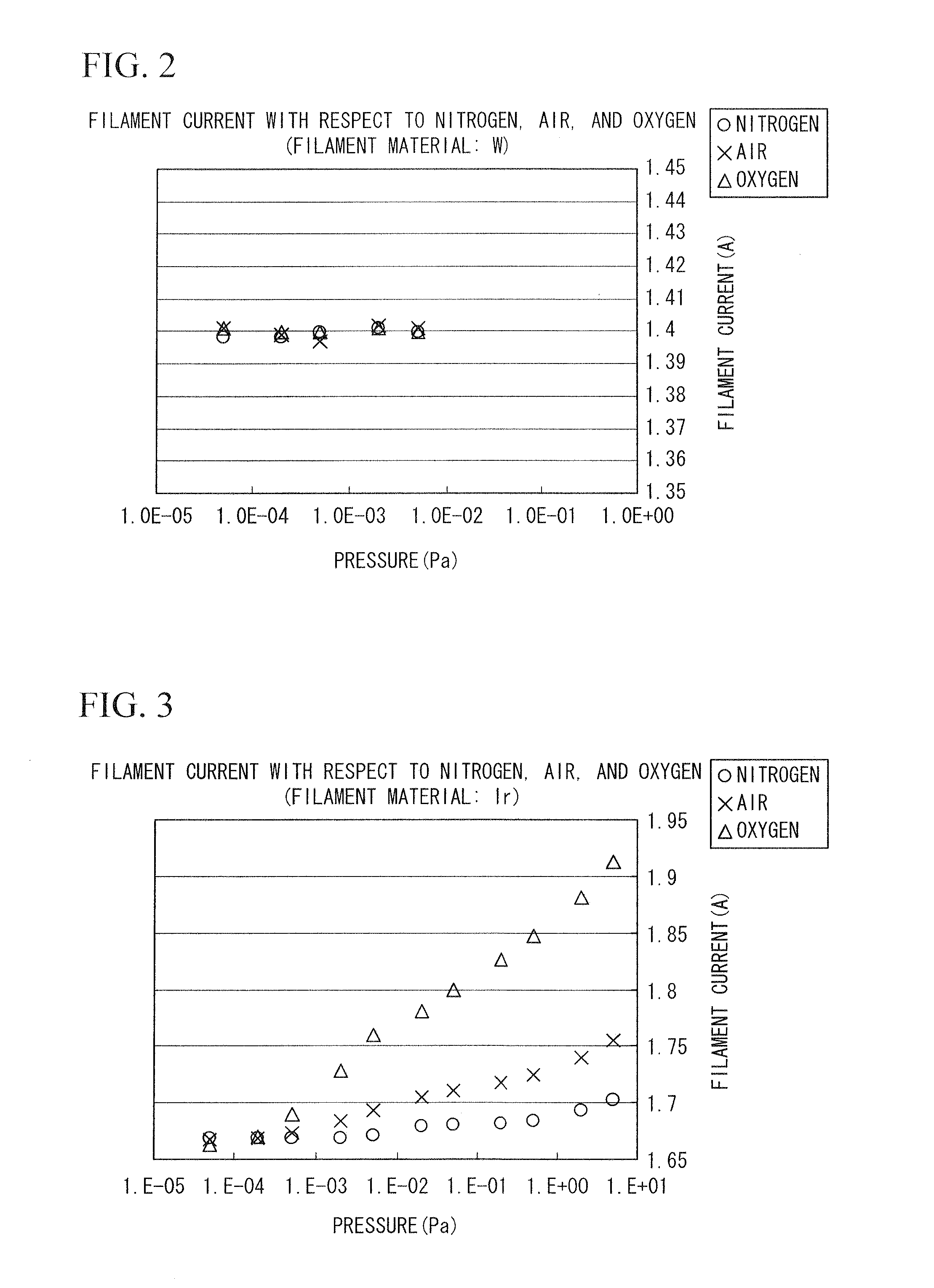
[0071]In FIGS. 2 and 3 to be described below, the horizontal axis indicates a pressure P, and the vertical axis indicates a filament current If.

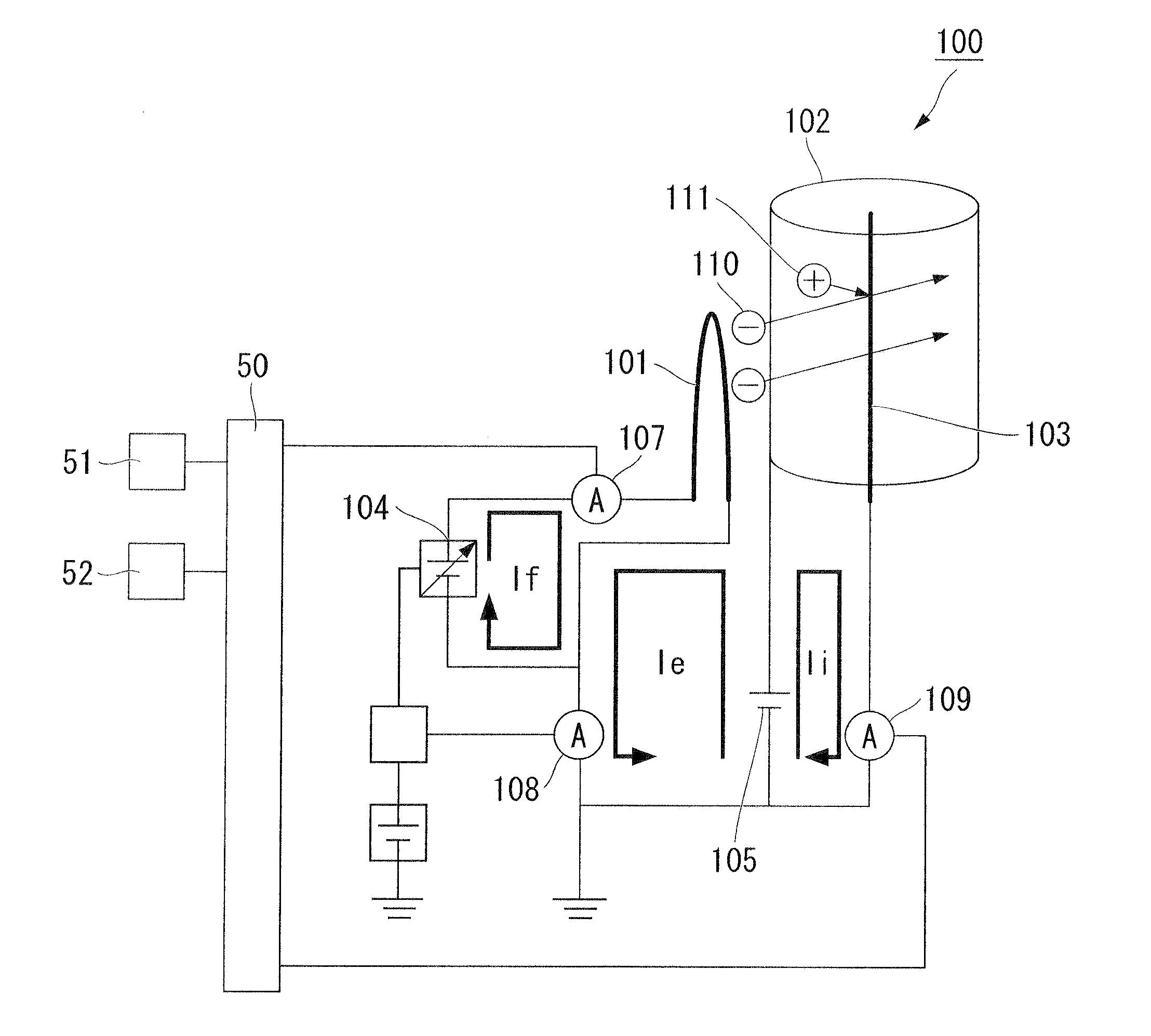
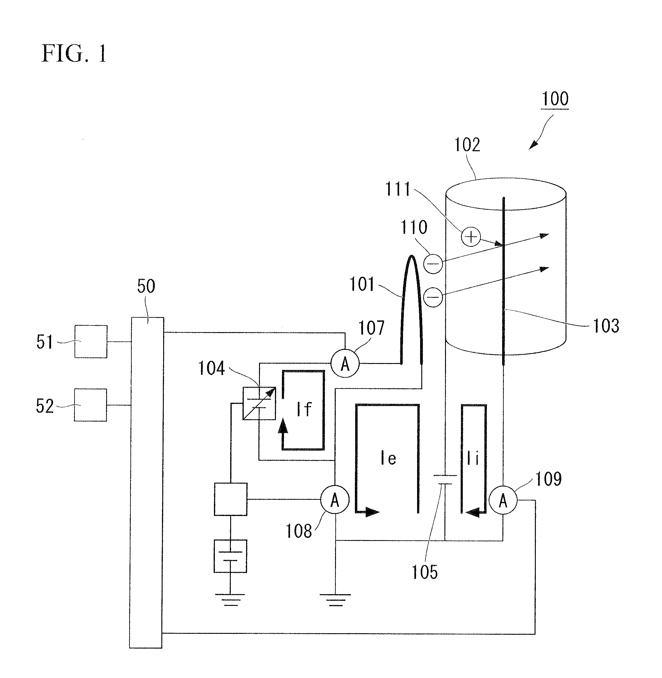
[0072]FIG. 2 illustrates a comparison result between the pressure P and the filament current If when nitrogen, air, and oxygen are introduced by using the gas component detection device 100 using tungsten (W) which has been used as a material of the filament 101 for some time.

[0073]As shown in FIG. 2, in the relationship between the pressure P and the filament current If, no difference was found between nitrogen, air, and oxygen.

[0074]Therefore, the ty...

experimental example 2

[0121]FIG. 4 is a diagram illustrating a temporal variation of the pressure and the filament current value measured in accordance with the above-described method.

[0122]In FIG. 4 to be described below, the horizontal axis indicates the time, and the vertical axis indicates the filament current If and the differential value of the filament current.

[0123]As shown in FIG. 4, it is found that the filament current value increases at the time when approximately 26 seconds have elapsed.

[0124]At the same time, it is apparent that the filament current value changes at the differential value of the filament current value.

[0125]That is, when it is detected that the pressure measured by the ionization vacuum gauge does not change and the differential value of the filament current is greater than or equal to a specified value, it is possible to determine air being present inside the vacuum processing chamber.

[0126]That is, it is possible to determine the abrupt leakage of air occurs.

[0127]In this...

experimental example 3

[0128]Recently, a vacuum gauge has been known in which an ionization vacuum gauge and a Pirani gauge that can be measured from the atmospheric pressure are assembled in the same vacuum processing chamber.

[0129]This vacuum gauge has a structure in which the pressure inside the vacuum processing chamber is measured by the Pirani gauge in the range from the atmospheric pressure to the pressure that can be detected by the ionization vacuum gauge, and the filament is automatically turned on when the pressure inside the vacuum processing chamber arrives at a pressure p1 (a measurable pressure p1) at which the pressure inside the vacuum processing chamber can be measured by the ionization vacuum gauge.

[0130]FIG. 5 is a diagram illustrating a relationship between a pressure and a time necessary for depressurization when the vacuum processing chamber is depressurized from an atmospheric pressure to a vacuum.

[0131]The time necessary from the start of the depressurization to the arrival of the...


PUM

PropertyMeasurementUnit
emission currentaaaaaaaaaa
filament currentaaaaaaaaaa
pressureaaaaaaaaaa

Abstract

An oxygen detection method, includes: preparing a grid, an ion collector, and a filament in which an oxide are formed on a surface of metal; controlling a filament current flowing to the filament so that an emission current becomes constant; discharging thermionic electrons which are caused by heat generation by applying the filament current, and generating ions by ionizing a gas; capturing the ions with the ion collector; and detecting oxygen being present in a vacuum processing chamber by measuring a filament current value.

Description

BACKGROUND OF THE INVENTION[0001]1. Field of the Invention[0002]The present invention relates to an oxygen detection method, an air leakage determination method, a gas component detection device, and a vacuum processing apparatus.[0003]Particularly, the invention relates to a method of efficiently detecting oxygen inside a vacuum processing chamber by controlling and measuring a filament current using an ionization vacuum gauge or a mass spectrometer, a method of determining a leakage of air, a gas component detection device used to perform the detection method or the determination method, and a vacuum processing apparatus including the gas component detection device.[0004]Priority is claimed on Japanese Patent Application No. 2009-066887, filed Mar. 18, 2009, the content of which is incorporated herein by reference.[0005]2. Background Art[0006]Conventionally, a hot cathode ionization vacuum gauge has been widely used to measure a pressure (a vacuum degree) inside a vacuum processin...

Claims


Application Information

Patent Timeline
Patent Type & Authority Applications(United States)
IPC IPC(8): H01J49/26G01N27/70
CPCG01N27/66G01M3/202
Inventor NAKAJIMA, TOYOAKIMIYASHITA, TAKESHINAGATA, YASUSHIUCHIDA, YASUFUMIYOSHIZAWA, HIDEKI
Owner ULVAC INC
Why Eureka
Try Eureka