Power capture system and method
- Summary
- Abstract
- Description
- Claims
- Application Information
AI Technical Summary
Benefits of technology
Problems solved by technology
Method used
Image
Examples
Embodiment Construction
[0089]Embodiments of the invention are now described, by way of non-limiting example, and are illustrated in the following figures:
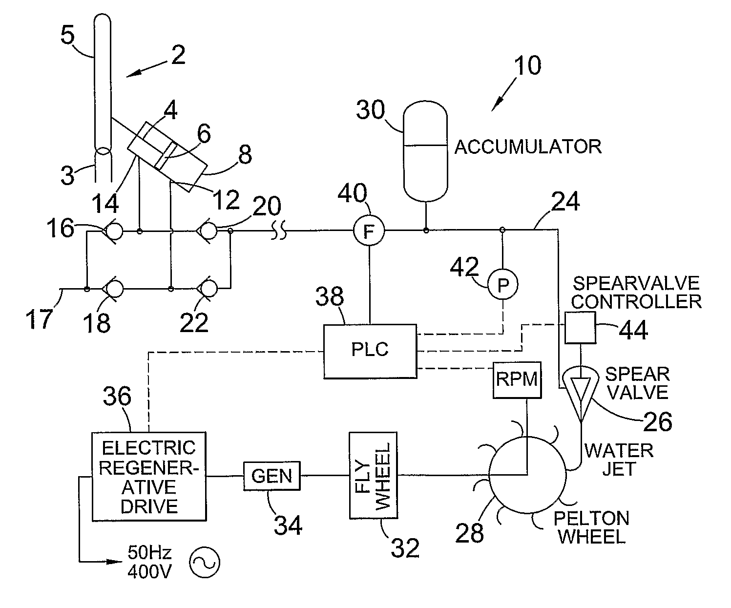
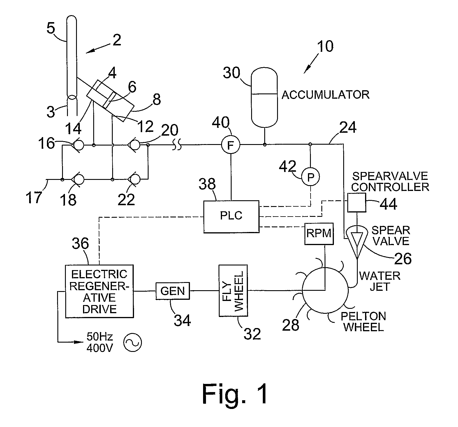
[0090]FIG. 1 is a schematic diagram of a wave power capture system;
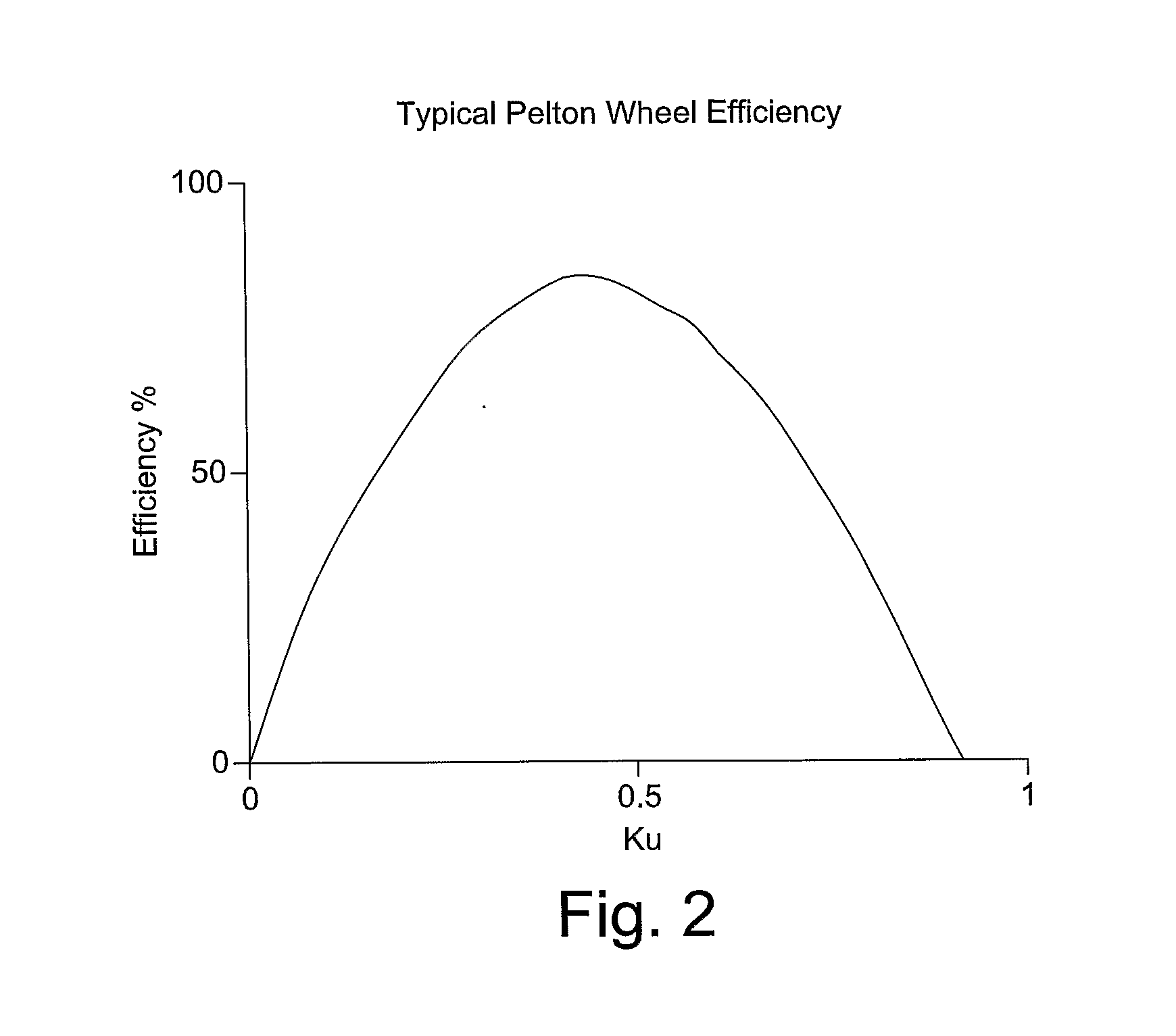
[0091]FIG. 2 is a graph of efficiency versus parameter Ku for a Pelton wheel;
[0092]FIG. 3 is flow chart illustrating in overview the control of operating speed and pressure in a short term control procedure, and the adjustment of an ideal pressure parameter in a long term control procedure, for the controller of the wave power capture system;
[0093]FIG. 4 is a more detailed flow chart illustrating a control procedure for the controller of the wave power capture system of FIG. 1;
[0094]FIG. 5 is a flow chart illustrating a self-optimisation process for tuning the system to the prevailing wave climate; and
[0095]FIG. 6 is a flow chart illustrating a start-up procedure and safety procedures for a mode of operation of the wave power capture system of FIG. 1.
[0096]FIG. 1 is a schematic illustrati...
PUM
 Abstract
Description
Claims
Application Information
 - R&D
- Intellectual Property
- Life Sciences
- Materials
- Tech Scout
- Unparalleled Data Quality
- Higher Quality Content
- 60% Fewer Hallucinations
Browse by: Latest US Patents, China's latest patents, Technical Efficacy Thesaurus, Application Domain, Technology Topic, Popular Technical Reports.
© 2025 PatSnap. All rights reserved.Legal|Privacy policy|Modern Slavery Act Transparency Statement|Sitemap|About US| Contact US: help@patsnap.com


