Method of tuning display chromaticity by mixing color filter materials and device having mixed color filter materials

a color filter and chromaticity technology, applied in the direction of discharge tube luminescnet screens, discharge tube/lamp details, electric discharge lamps, etc., can solve the problems of not always being able to achieve the desired thickness of a color filter layer, not always being able to achieve the desired transmittance, etc., to reduce unwanted light output, improve the white balance of the display, and reduce the transmittance of visible light

Active Publication Date: 2011-12-29
EMAGIN CORP
View PDF2 Cites 55 Cited by
  • Summary
  • Abstract
  • Description
  • Claims
  • Application Information

AI Technical Summary

Benefits of technology

[0029]A method of white-balancing a light emitting device having a plurality of sub-pixels having color filters is provided. The method includes providing a red sub-pixel, a green sub-pixel and a blue sub-pixel, each sub-pixel having a base electrode, a transparent electrode, and a light-emissive layer interposed between the base electrode and the transparent electrode. The method also includes providing a filter layer for each sub-pixel arranged so that the transparent electrode is interposed between the filter layer and the emissive layer of the respective sub-pixel. A filter layer for the green sub-pixel includes a green filter material and a blue filter material and / or a red filter material. The method further includes selecting a proportion of the green filter material to the blue filter material and / or the red filter material in the green filter layer to improve a white balance of the display compared to a further display having a further green filter layer including only the green filter material.
[0030]A method of reducing unwanted light output due to electrical leakage in a light emitting device having a plurality of sub-pixels having color filters is provided. The method includes providing a color filter for at least one of the sub-pixels having at least first and second color filter materials. The first color filter material is adapted to reduce transmittance of visible light outside a first transmittance spectrum corresponding to a first color, and the second color filter material is adapted to reduce transmittance of visible light outside a second transmittance spectrum corresponding to a second color. The second color is different than the first color, and the color filter has a transmittance causing a luminosity due to electrical leakage into the at least one sub-pixel to fall below a pre-determined threshold.

Problems solved by technology

This approach is appropriate for large size displays, but has certain difficulties in being implemented in color displays where pixel and sub-pixel dimensions are on the scale of micrometers.
However, it is not always possible to attain the desired thickness of a color filter layer due to the limitations in photolithography techniques, spin coating processes, and the properties of the color filter material.
It may not be possible to achieve a desired transmittance simply by reducing or increasing a thickness of a layer due to the limits on varying a thickness of a spin coated film.
Another problem in balancing OLED display colors may arise when the separation between two adjacent pixels or sub-pixels are being reduced to the micrometer or sub-micrometer dimensions.
One common obstacle for all the above mentioned technologies is the possibility of increased leakage current with increasing density and decreasing circuit elements size, irrespective of the OLED stack.
While leakage current may be very low and random, on the order of nano- or even pica-Amperes, it may still affect performance of an OLED display.
For example, even if all green sub-pixels are turned off, and only red sub-pixels are turned on, the leakage current through green sub-pixels may skew the otherwise pure red color emission produced by the red sub-pixels.

Method used


Image

  • Method of tuning display chromaticity by mixing color filter materials and device having mixed color filter materials
  • Method of tuning display chromaticity by mixing color filter materials and device having mixed color filter materials
  • Method of tuning display chromaticity by mixing color filter materials and device having mixed color filter materials

Examples


Embodiment Construction

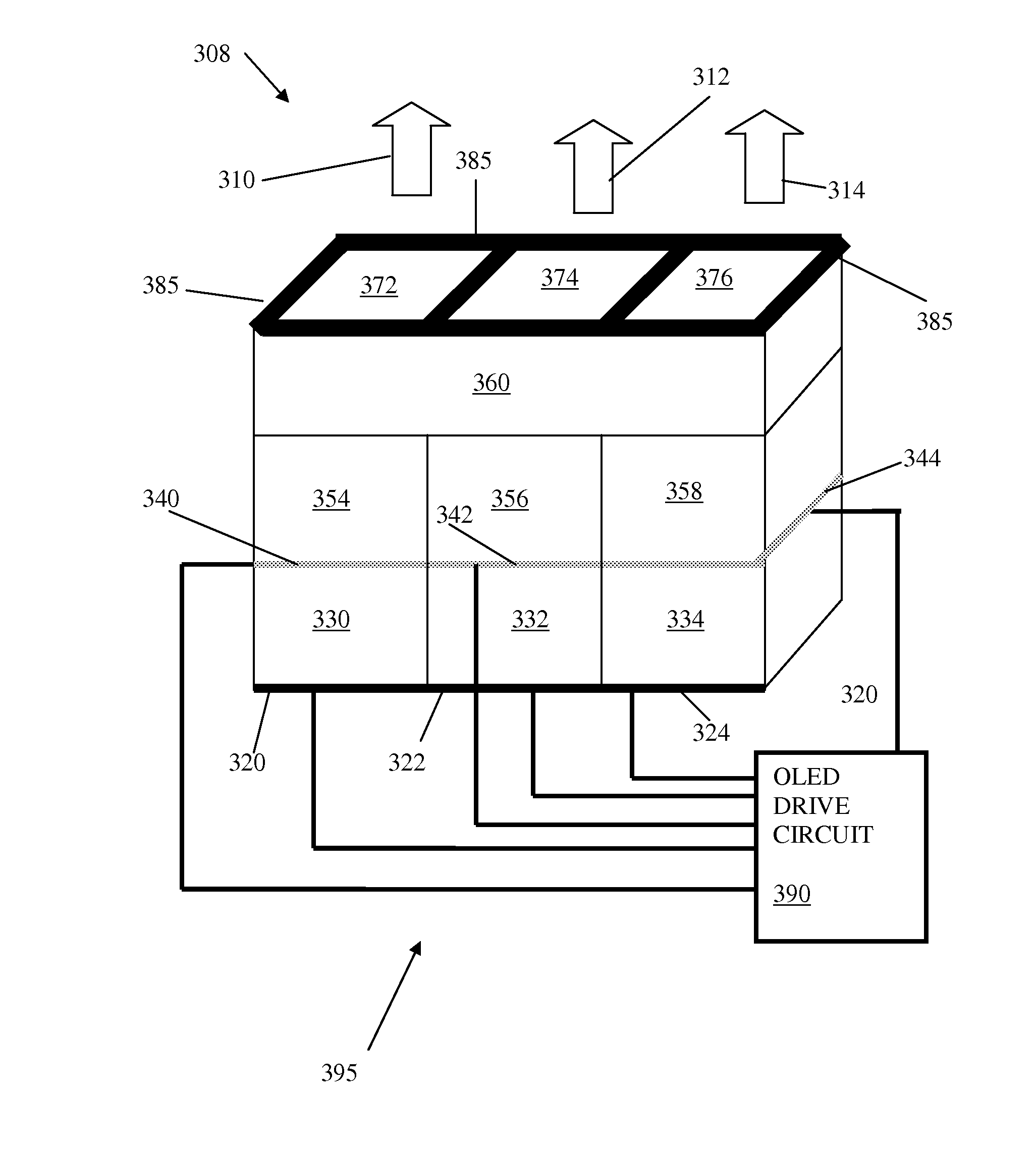
[0047]The present invention proposes to use mixtures of at least two or more color filter materials in one layer, or in combination with individual color filter layers. The layer or layers will be deposited on at least one sub-pixel within a group of three RGB sub-pixels to subdue parasitic contribution of emission due to electrical current leakage from an inactive sub-pixel.

[0048]The present invention proposes to use mixtures of at least two or more color filter materials in one layer, or in combination with individual color filter layers which will be deposited on at least one sub-pixel within a group of three RGB sub-pixels or between the sub-pixels. The present invention proposes to use mixtures of at least two or more color filter materials to construct a single opaque layer that can be placed on desired locations on OLED display to block undesired emission across entire visible optical band.

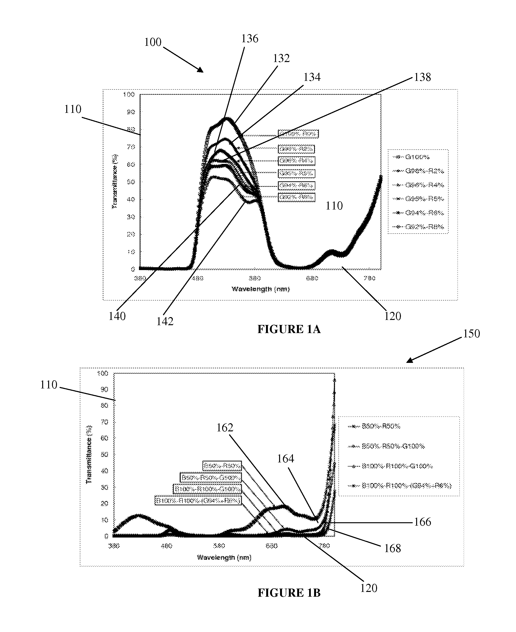
[0049]FIG. 1A is graph 100 of transmittance with respect to wavelength for exemplary gr...


PUM


Abstract

A color display is provided that includes a light emitting sub-pixel and a filter layer including first and second color filter materials. The first color filter material is adapted to reduce transmittance of visible light outside a first transmittance spectrum corresponding to a first color, and the second color filter material is adapted to reduce transmittance of visible light outside a second transmittance spectrum corresponding to a second color. The second color is different than the first color. A color display having a white-balanced pixel is provided. A method of white-balancing a light emitting device is provided. A method of reducing unwanted light output due to electrical leakage is provided to fall below a pre-determined threshold. An opaque layer may be interposed between the sub-pixels and/or may frame illuminated areas of sub-pixels, and may be a combination of red, green, and/or a blue filter material.

Description

CROSS-REFERENCE TO RELATED APPLICATIONS[0001]This application claims the benefit of U.S. Provisional Application No. 61 / 358,510 filed Jun. 25, 2010, which is incorporated herein by reference.STATEMENT REGARDING FEDERALLY SPONSORED RESEARCH OR DEVELOPMENT[0002]Not ApplicableBACKGROUND OF THE INVENTION[0003]1. Field of the Invention[0004]The present invention relates to light emitting devices. In particular, the present invention relates to a filter design for organic light emitting diode (“OLED”) devices.[0005]2. Description of the Related Art[0006]An OLED device typically includes a stack of thin layers formed on a substrate. In the stack, a light-emitting layer of a luminescent organic solid, as well as adjacent semiconductor layers, is sandwiched between a cathode and an anode. The light-emitting layer may be selected from any of a multitude of fluorescent organic solids. Any of the layers, and particularly the light-emitting layer, may consist of multiple sub layers.[0007]In a ty...

Claims


Application Information

Patent Timeline
Patent Type & Authority Applications(United States)
IPC IPC(8): H01J1/62
CPCH01L51/5284H01L27/322H10K59/38H10K50/865
Inventor GHOSH, AMALKUMAR P.ZIESMER, SCOTTKHAYRULLIN, ILYAS
Owner EMAGIN CORP
Why Eureka
Try Eureka