Lubrication of a planetary gear device

a gear device and planetary technology, applied in the direction of electric propulsion mounting, gearing, transportation and packaging, etc., can solve the problems of complicated apparatus configuration and difficult control in the related-art technology

Active Publication Date: 2011-12-29
TOYOTA JIDOSHA KK
View PDF6 Cites 10 Cited by
  • Summary
  • Abstract
  • Description
  • Claims
  • Application Information

AI Technical Summary

Benefits of technology

[0013]This invention, in a vehicle motive power transmission apparatus that transmits rotation power generated by a motive power source to the output side via a planetary gear devic

Problems solved by technology

Therefore, the control in the related-art technology is not ea

Method used


Image

  • Lubrication of a planetary gear device
  • Lubrication of a planetary gear device
  • Lubrication of a planetary gear device

Examples


Embodiment Construction

[0036]Embodiments of the invention will be described in detail hereinafter with reference to the accompanying drawings.

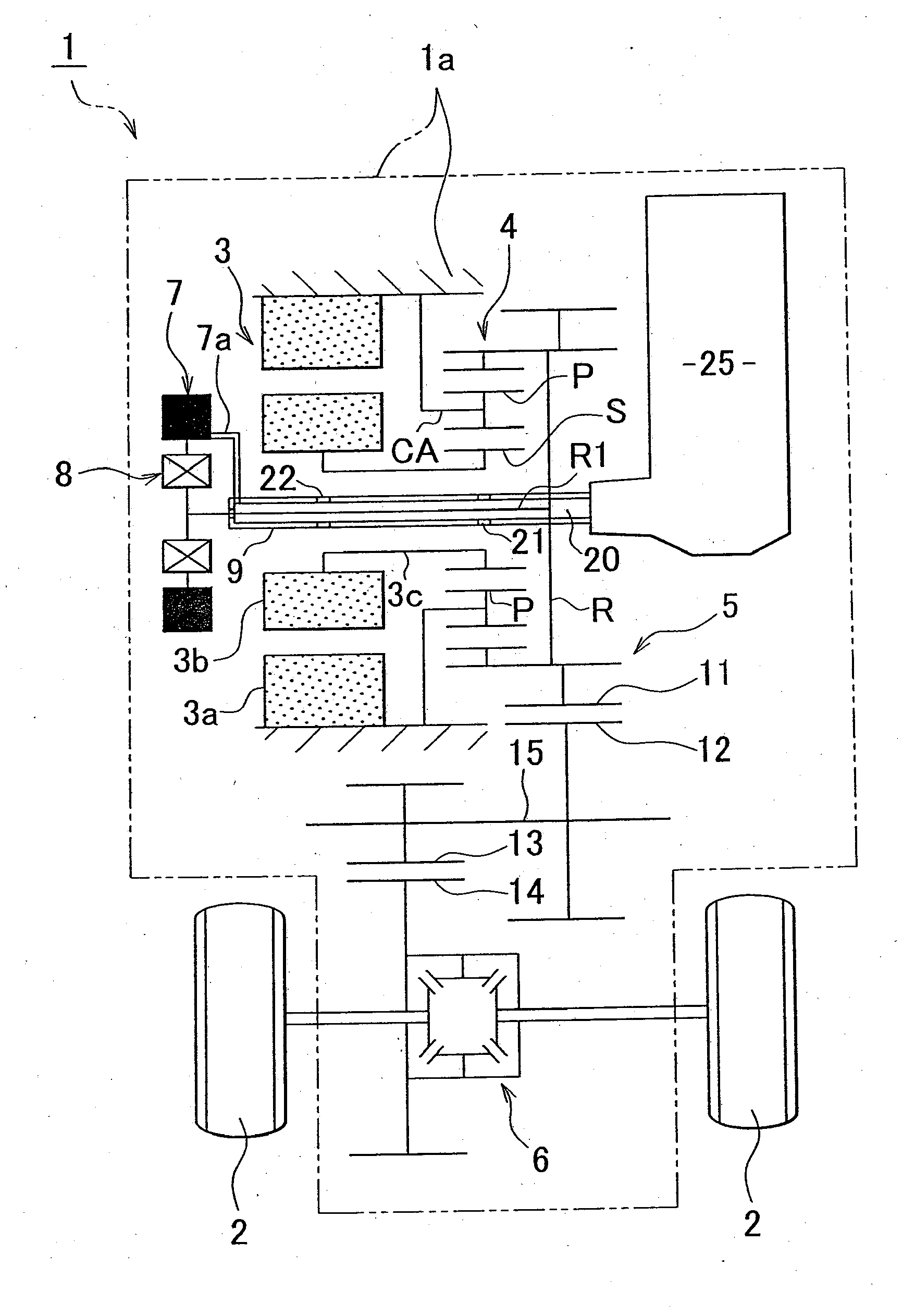
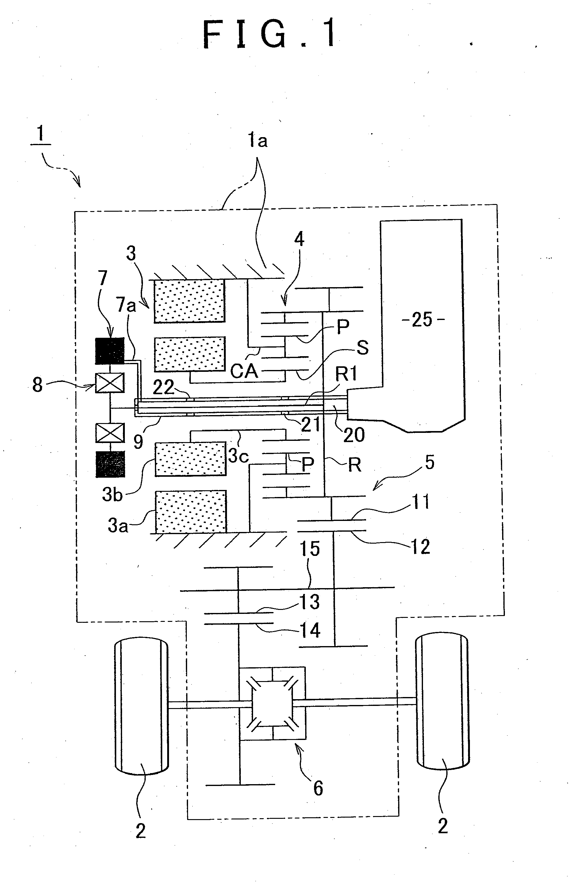
[0037]An embodiment of the invention is shown in FIG. 1 to FIG. 3. Firstly, a general construction of a transaxle for an electric motor vehicle which is an embodiment of the vehicle motive power transmission apparatus in accordance with the invention.

[0038]In FIG. 1, a transaxle 1 and wheels 2 are shown. The transaxle 1 mainly includes an electric motor 3 as a motive power source, a planetary gear device 4, a speed reduction gear mechanism 5, and a differential device (final speed reducer) 6.

[0039]This transaxle 1 is constructed so as to transmit rotation power generated by the electric motor 3 to the differential device 6 via the planetary gear device 4 and the speed reduction gear mechanism 5, and transmit the rotation power from the differential device 6 to the wheels 2, 2 as forward travel drive force or reverse travel drive force.

[0040]The electric motor 3 incl...


PUM


Abstract

A vehicle motive power transmission apparatus includes: a planetary gear device; an oil pump for sucking oil present in an apparatus case; a one-way clutch that transmits normal-direction rotation output of the planetary gear device to the oil pump, but does not transmit reverse-direction rotation output of the planetary gear device to the oil pump; an oil tank which is provided in the apparatus case, and which is provided with a first introduction portion that receives oil that is splashed upward as a gear in the apparatus case rotates in a normal direction, and a second introduction portion that receives oil that is splashed upward as the gear rotates in a reverse direction; and an oil passageway that supplies the planetary gear device with oil present in the oil tank or oil sucked by the oil pump.

Description

BACKGROUND OF THE INVENTION[0001]1. Field of the Invention[0002]The invention relates to a motive power transmission apparatus for a vehicle which transmits rotation power that is generated by a motive power source to an output side via a planetary gear device. In particular, the invention relates to a technology of supplying oil to such a planetary gear device.[0003]2. Description of the Related Art[0004]There have been motive power transmission apparatuses for vehicles which transmit rotation power generated by, for example, an electric motor, to wheels via a planetary gear device (e.g., see Japanese Patent Application Publication No. 2007-195320 (JP-A-2007-195320)).[0005]Regarding a related-art technology according to Japanese Patent Application Publication No. 2007-195320 (JP-A-2007-195320), the abstract in the publication states “A geared motor 10G, obtained by disposing an electric motor 10 behind a speed reducing gear mechanism 11, is used as an in-wheel motor disposed at the...

Claims


Application Information

Patent Timeline
IPC IPC(8): F16H57/04F16H48/06B60K1/00
CPCB60K1/00B60K6/26B60K17/356B60K2001/001B60K2001/003F16H57/0409Y02T10/6265F16H57/0434F16H57/045F16H57/0457F16H57/0476F16H57/0486F16H57/0423Y02T10/62
Inventor KATOH, SHINGONISHIGAYA, MASABUMI
Owner TOYOTA JIDOSHA KK
Why Eureka
Try Eureka