Device and Method for Fixing a Component in Position on a Component Carrier

a technology of component carrier and component, which is applied in the direction of glue vessel, manufacturing tools, chemistry apparatus and processes, etc., can solve the problems of carrier surface permeability, weak adhesive bond, and technical complexity required for the device, and achieve strong adhesive bond

Active Publication Date: 2012-01-05
MTU AERO ENGINES GMBH
View PDF3 Cites 8 Cited by
  • Summary
  • Abstract
  • Description
  • Claims
  • Application Information

AI Technical Summary

Benefits of technology

[0007]It is an object of the present invention to provide a device and a method for fixing a component in position on a component carrier that will overcome the aforementioned disadvantages and make possible an exceptionally strong adhesive bond.
[0010]In this approach, the radiation is not directed at a component carrier-side adhesive surface to then penetrate therethrough into the adhesive agent; rather, the adhesive agent is laterally irradiated in accordance with the present invention. One advantage of lateral radiation is that the material used for forming the bonding surface is freely selectable and is not limited to glass, for example. This permits a substantially greater design freedom for the component carrier, so that only low production costs arise in the process.
[0011]The bonding surface of the component carrier is made of a radiation-impervious material. This permits the use of materials, such as tool steel, which allow a greater bond strength in comparison to known bonding surfaces of glass. It is thus possible to reduce the size of the bonding surface and, in particular, the quantity of the adhesive agent, or to increase the adhesive force per surface area.
[0012]In one exemplary embodiment, the bonding surface is band-shaped or striated. This band-shaped bonding surface form, which is narrow in comparison to the component, allows the radiation to propagate readily through the adhesive agent, thereby making possible a reliable curing. The bonding surface is preferably configured close to the contour of a component section to be accommodated, so that a uniform adhesive gap is adjustable therebetween.
[0015]In another exemplary embodiment, the component carrier features a mesh structure for applying the adhesive agent. A plurality of web-type, respectively linear bonding surfaces are hereby devised. The radiation source is preferably positioned at a mesh structure side that faces away from the component. Alternatively, two radiation sources may also be provided, an opening being provided in each case in the area of the radiation sources. The radiation is reflected in the intermediate spaces, respectively mesh apertures of the mesh structure, so that the reflection and the web-type form of the bonding surfaces allow the adhesive agent to cure even in the shadows of the mesh structure.
[0016]To adjust the particular adhesive gap between the component carrier and the component, it is advantageous from a standpoint of production engineering for the component carrier to be provided with spacer elements for supporting the component.

Problems solved by technology

This known approach does, in fact, allow the turbine blade to be securely fixed in position; however, heat generated during processing can weaken the adhesive bond.
The drawback of this affixing method is that the component carrier has a bonding surface that is permeable to UV radiation, for example.
The particular disadvantage of this approach is the technical complexity required for the devices.

Method used


Image

  • Device and Method for Fixing a Component in Position on a Component Carrier
  • Device and Method for Fixing a Component in Position on a Component Carrier
  • Device and Method for Fixing a Component in Position on a Component Carrier

Examples


Embodiment Construction

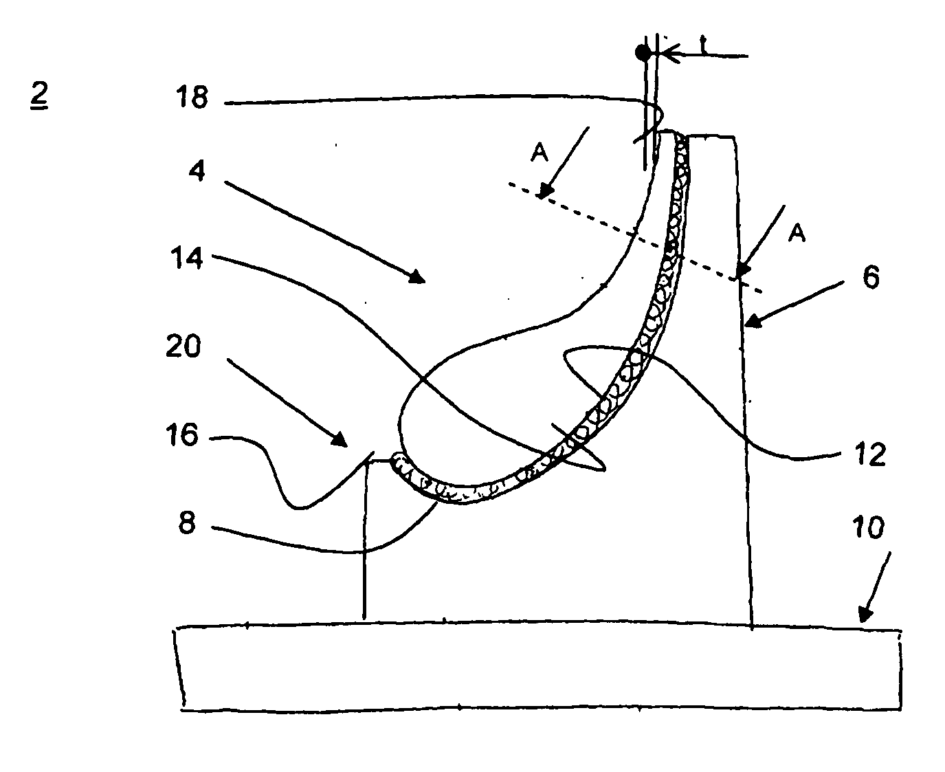
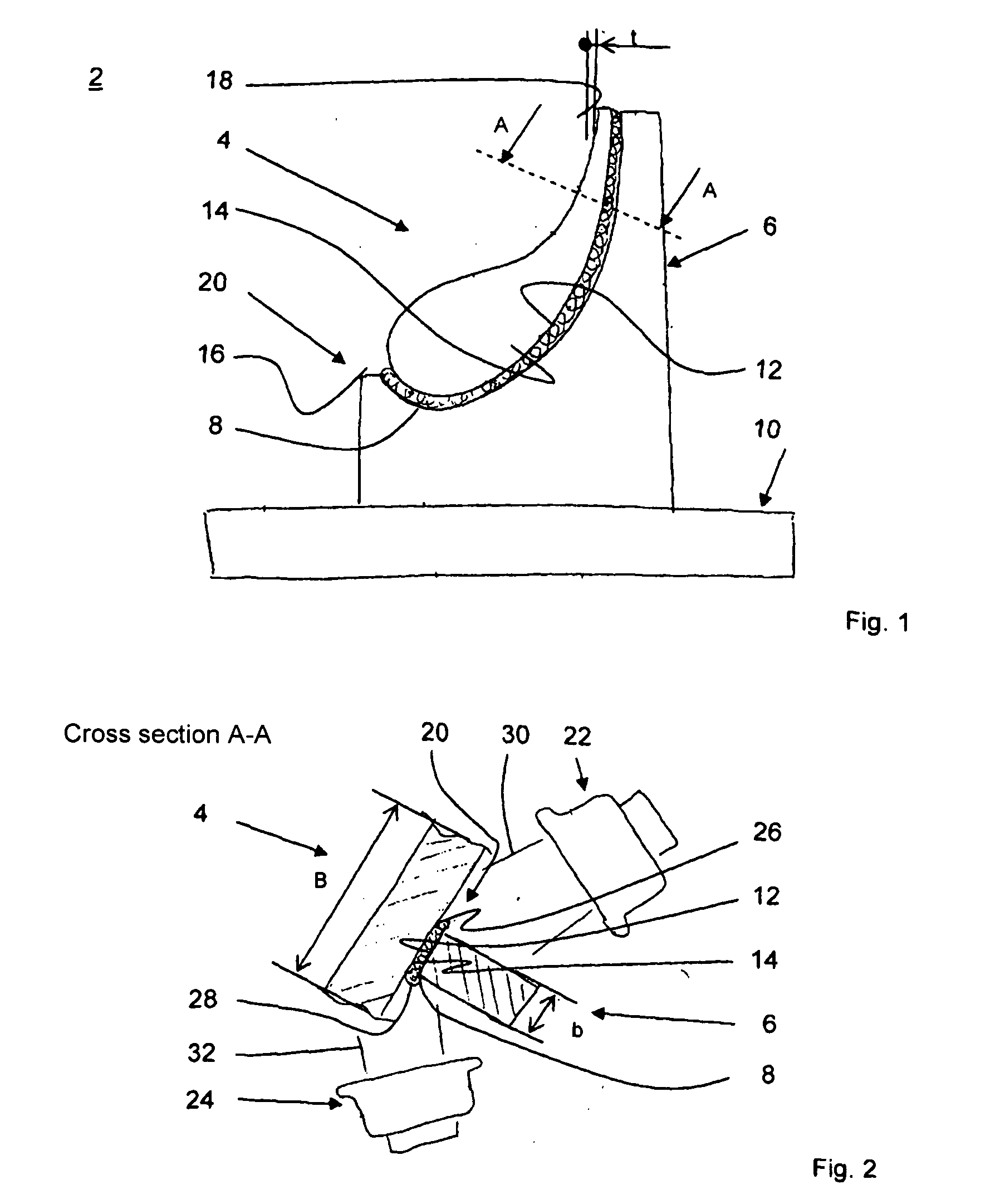
[0023]FIG. 1 shows a side view of a first device 2 according to the present invention for fixing a component 4 in position in a component carrier 6 using adhesive bonding. Component 4 is shown exemplarily as a blade of a turbine, in particular of an aircraft engine, and is referred to as such in this and in the further exemplary embodiments. The adhesive bond is based on a radiation-activable adhesive agent 8 that is curable, respectively releasable, in particular, by electromagnetic radiation.

[0024]Component carrier 6 is mounted on a base plate 10 and features a concave, respectively sickle-shaped bonding surface 12 for receiving blade 4. Bonding surface 12 is configured close to the contour of a convex intake-side portion 14 of blade 4 facing it. In the illustrated exemplary embodiment, bonding surface 12 extends from a leading edge 16 of blade 4 to a trailing edge 18.

[0025]Blade 4 is fixed in position using adhesive agent 8 which is placed between bonding surface 12 and intake-si...


PUM

PropertyMeasurementUnit
structureaaaaaaaaaa
adhesiveaaaaaaaaaa
areaaaaaaaaaaa

Abstract

A device for fixing a component (4) in position on a component carrier (6) using a radiation-curing adhesive agent (8), in which case the radiation (30, 32) for curing the adhesive agent (8) located between the component carrier (6) and the component (4) is laterally introducible; as well as a method for fixing a component (4) in position in a component carrier (6) using an adhesive bond.

Description

[0001]The present invention relates to a device for fixing a component in position on a component carrier, and to a method for fixing a component in position on such a component carrier.BACKGROUND[0002]Components often pass through a multitude of processing stations before reaching their finished form. To position the components in the processing stations, component carriers are used in which the components are secured. The process of fixing the components in position in the component carriers must be rapid and reliable, and the components must be readily releasable.[0003]The German Patent Application DE 10 2007 020 957 A1 of the Applicant provides for fixing a turbine blade in position on a component carrier using a bonded connection, for example. The component carrier has a contour-close bonding surface, onto which an adhesive agent is applied over a large area. Once the adhesive agent is applied, the turbine blade is positioned on the component carrier, and the adhesive agent is ...

Claims


Application Information

Patent Timeline
Patent Type & Authority Applications(United States)
IPC IPC(8): B32B37/06B32B37/12
CPCB23Q3/084
Inventor FESSLER-KNOBEL, MARTINHUTTNER, ROLAND
Owner MTU AERO ENGINES GMBH
Why Eureka
Try Eureka