Power generator using a wind turbine, a hydrodynamic retarder and an organic rankine cycle drive

a technology of hydrodynamic retarder and rankine cycle, which is applied in the direction of electric generator control, machine/engine, greenhouse gas reduction, etc., can solve the problems that the rankine cycle may not be practical to implement with a wind turbine, and the known wind turbine may not produce enough waste heat to drive even modified versions of the rankine cycle. , to achieve the effect of enhancing the heat to power efficiency of the rankine cycle, facilitating inspection and maintenance of the generator, and reducing heat loss

Inactive Publication Date: 2012-01-05
SAMI SAMUEL DR
View PDF0 Cites 99 Cited by
  • Summary
  • Abstract
  • Description
  • Claims
  • Application Information

AI Technical Summary

Benefits of technology

[0016]In another aspect of the invention, the organic heat exchange fluid includes quaternary refrigerant organic mixtures operative at temperatures between about 23° C. to about 160° C. within the Rankine cycle drive. Such relatively low operating temperatures may allow polymeric piping or other plumbing of the Rankine cycle drive to extend further from the heat source, which may allow the generator to be located outside of a nacelle of the wind turbine, for example, on the ground or other location that facilitates easy inspection and maintenance of the generator. The polymeric piping may be an insulated, duplex, polymeric pipe that carries the quaternary refrigerant organic mixtures from hydrodynamic retarder to and from the waste boiler. Such polymeric pipe may reduce heat loss within portions of the system in which the polymeric pipe is used. Doing so may enhance the heat to power efficiency of the Rankine cycle. Connecting the Rankine cycle components and hydrodynamic retarder with polymeric pipe may also facilitate maintenance and inspection of the Rankine cycle components, electrical power generator, and gear box by allowing them to be fluidly connected while being mounted outside of a wind turbine nacelle; for example, while housed within a stand-alone service building near a tower base of a wind turbine, in a readily accessible portion of the tower, or other suitable location that is outside of the nacelle.

Problems solved by technology

The present inventors have recognized that a conventional Rankine Cycle may not be practical to implement with a wind turbine because of the large amount of heat that is required to drive the process.
The inventors have further recognized that known wind turbines may not produce sufficient waste-heat to drive even modified versions of the Rankine Cycle, such an organic Rankine Cycle, even though such an organic Rankine Cycle may be operable with relatively less heat input than the conventional Rankine Cycle.

Method used


Image

  • Power generator using a wind turbine, a hydrodynamic retarder and an organic rankine cycle drive
  • Power generator using a wind turbine, a hydrodynamic retarder and an organic rankine cycle drive
  • Power generator using a wind turbine, a hydrodynamic retarder and an organic rankine cycle drive

Examples


Embodiment Construction

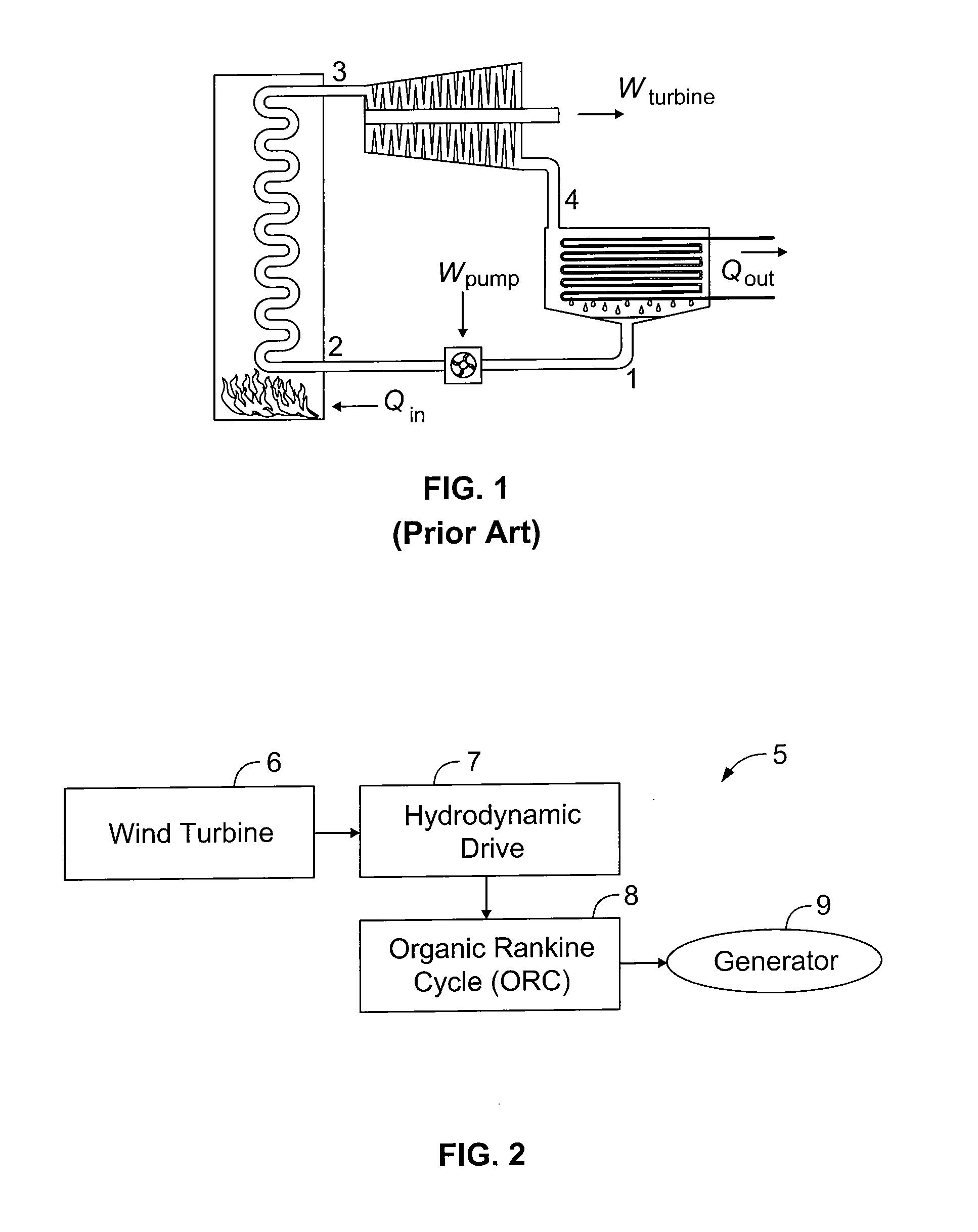
[0039]Referring now to the drawings and more particularly to FIG. 2, a schematic illustration of an electric power generation system 5 of the preferred embodiments is shown. A wind turbine 6 is provided and supplies harnessed energy to a hydrodynamic drive 7. Drive 7 works together with an ORC 8 to provide an output supplied to, for instance, an electric generator 9. Details of the power generation system of the preferred embodiments are provided hereinafter.

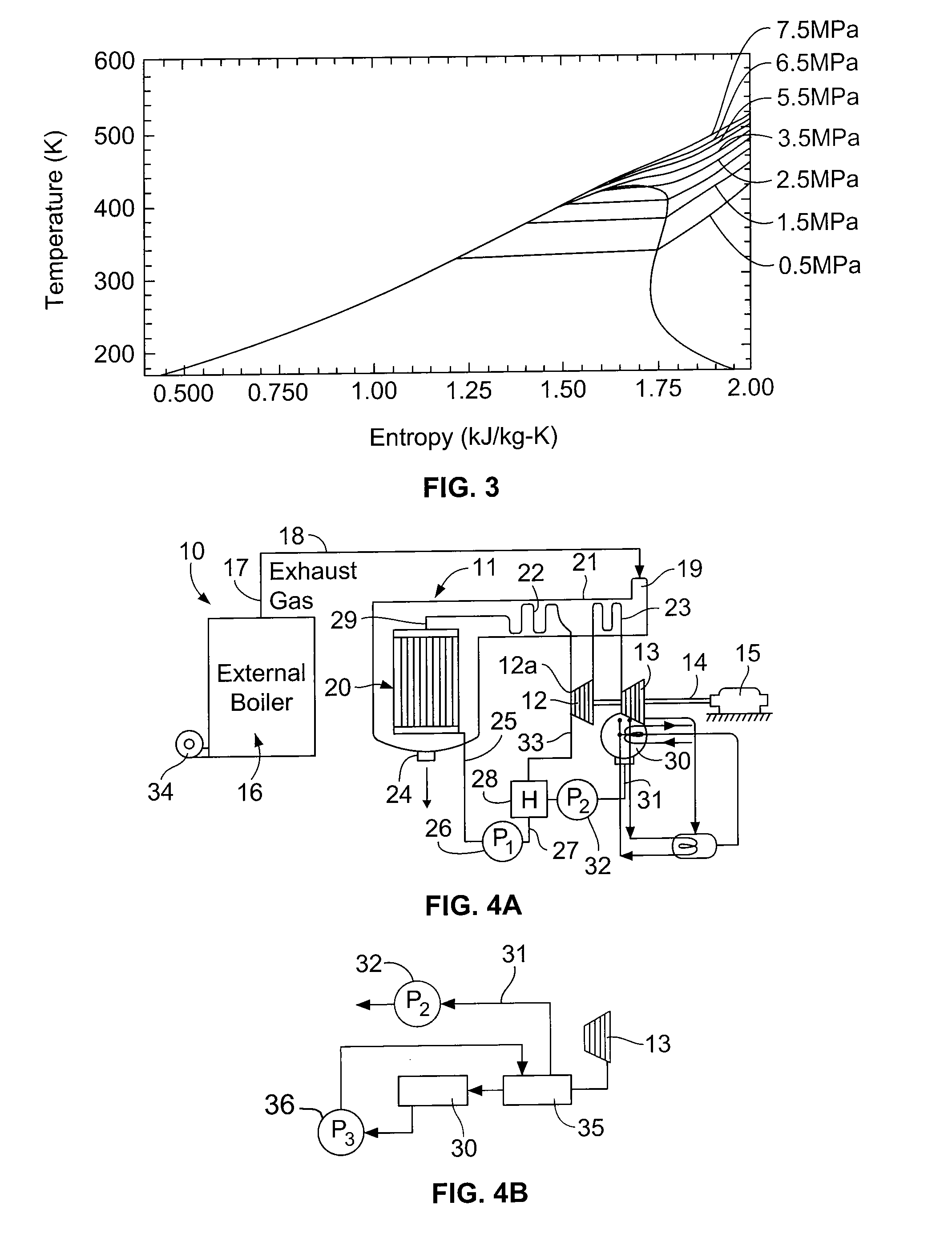
[0040]Turning now to FIG. 4A, there is shown generally at 10 an electric power generating system which has been adapted for the present invention (shown more completely in FIGS. 6 and 7, discussed below). It includes a waste-heat boiler 11 which is adapted to equipment normally found in a Rankine cycle system to power turbines. A high pressure turbine 12 and a low pressure turbine 13 cooperate with the waste-heat boiler 11 and are connected to a common drive shaft 14 of electric generator 15 to generate electric power.

[0041]Stil...


PUM


Abstract

An electric power generating system is provided that uses a wind turbine to generate waste-heat that is utilized in an organic Rankine Cycle drive that converts heat energy into rotation of a generator rotor for generating electricity. A hydrodynamic retarder may be provided that dissipates heat into a hot fluid by directing the flow of the fluid through the hydrodynamic retarder in a manner that resists rotation of blades of the wind turbine. The hot fluid circulating in the hydrodynamic retarder is a thermal heat source for vapor regeneration of organic heat exchange fluid mixture(s) used in the Rankine cycle, expansion of the organic heat exchange fluid being converted into rotation of the generator rotor.

Description

CROSS REFERENCE TO RELATED APPLICATION[0001]This Non-Provisional Application claims the benefit of and priority to U.S. Provisional Patent Application Ser. No. 61 / 360,704, filed Jul. 1, 2010, which is expressly incorporated by reference herein in its entirety, as if fully set forth herein.BACKGROUND OF THE INVENTION[0002]1. Field of the Invention[0003]The present invention relates to electric power generating systems, and more specifically, to wind-powered electric power generating systems, as well as corresponding methods of producing electric power from wind.[0004]2. Description of the Related Art[0005]As understood, there is an urgent need for renewable energy. The renewable energy industry has experienced dramatic changes over the past few years. Deregulation of the electricity market failed to solve the industry's problems. Also, unanticipated increases in localized electricity demands and slower than expected growth in generating capacity have resulted in an urgent need for al...

Claims


Application Information

Patent Timeline
Patent Type & Authority Applications(United States)
IPC IPC(8): F01K25/08F03D9/00F01K23/16
CPCF01K7/22F01K25/08Y02E10/725F03D9/00F01K27/02Y02E10/72Y02E70/30Y02P80/10F03D9/18F03D9/22
Inventor SAMI, SAMUEL M.WILSON, EDWIN E.BRATEL, DEAN J.BATTEN, JOHN H.
Owner SAMI SAMUEL DR
Why Eureka
Try Eureka