Controller for ac rotary machine

Active Publication Date: 2012-01-05
MITSUBISHI ELECTRIC CORP
View PDF4 Cites 22 Cited by
  • Summary
  • Abstract
  • Description
  • Claims
  • Application Information

AI Technical Summary

Benefits of technology

[0015]As described above, the controller for an AC rotary machine according to the first and second aspects of the present invention includes deviation vector calculation means for calculating a magnetic flux deviation vector which is a deviation between the estimated magnetic flux vector and the detected magnetic flux vector, and the output is inputted to the adaptive observation means. Therefore, irrespective of the magnitude of the rota

Problems solved by technology

However, if this method is used to drive the AC rotary machine in a high-rotation region, voltages or currents having a frequency other than the fundame

Method used


Image

  • Controller for ac rotary machine
  • Controller for ac rotary machine
  • Controller for ac rotary machine

Examples


embodiment 1

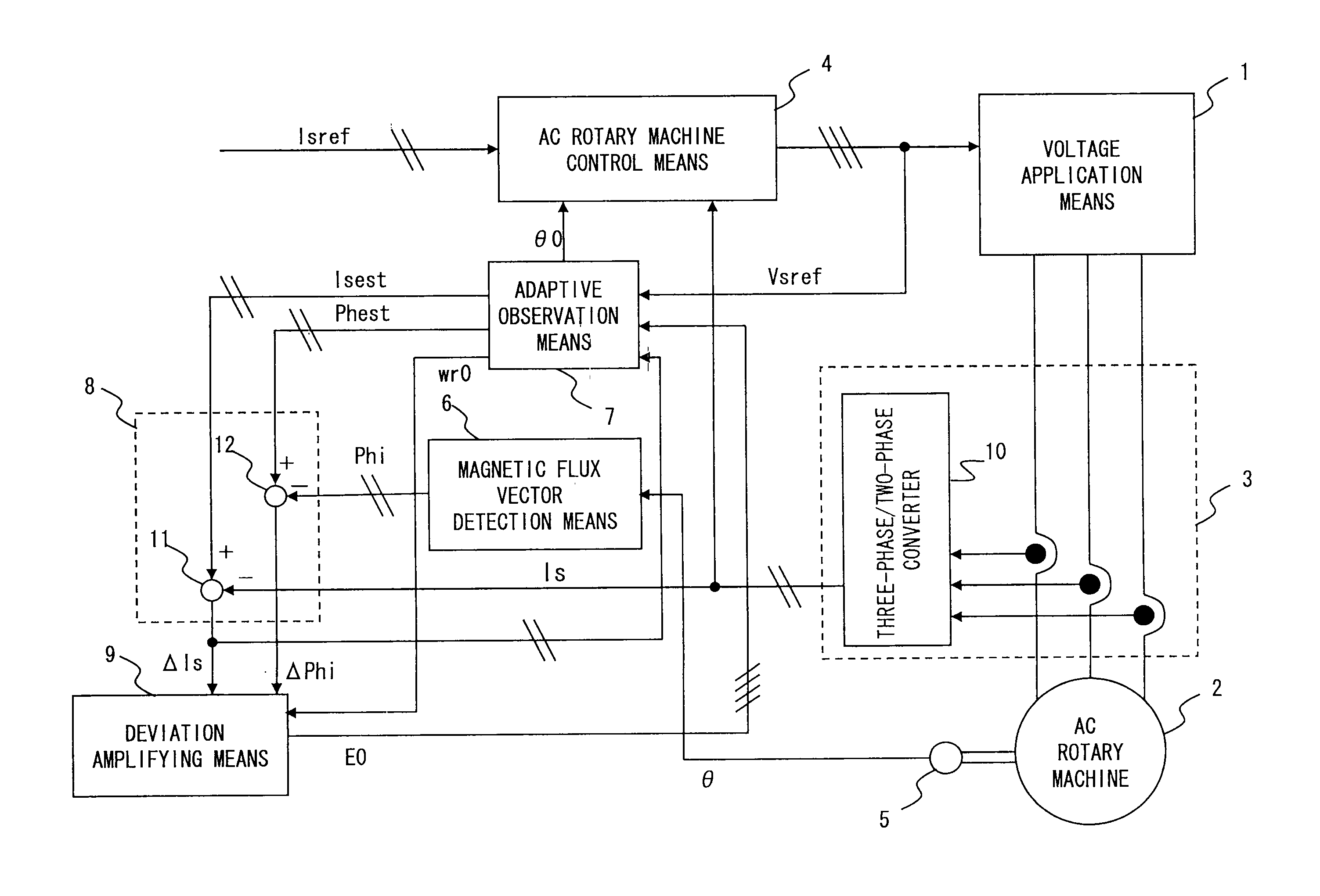
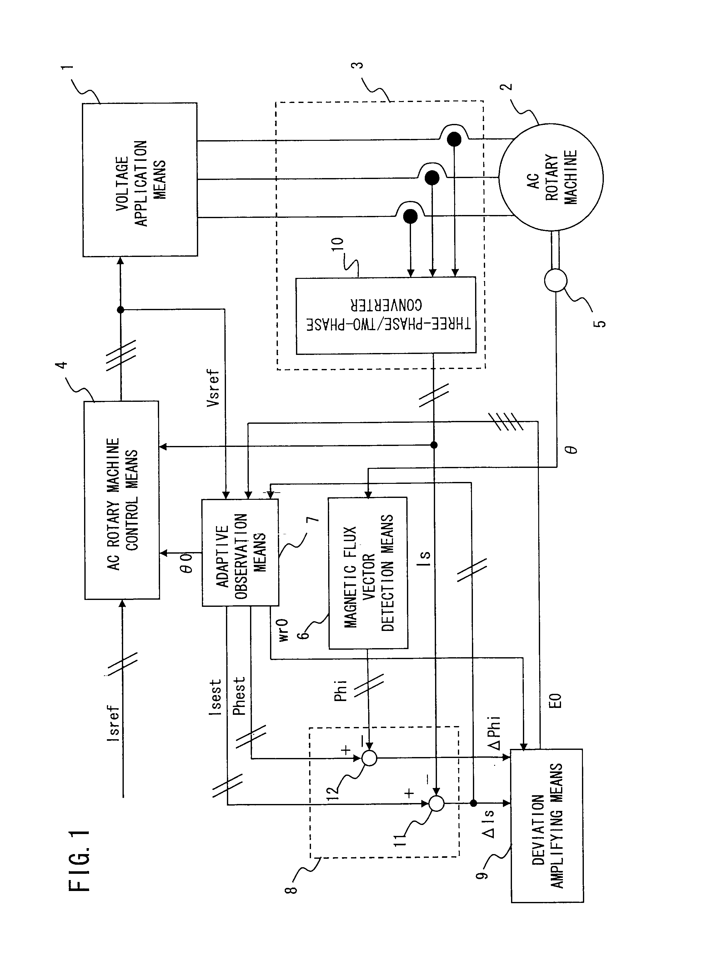
[0039]FIG. 1 is a diagram showing an entire configuration according to the present embodiment 1. In FIG. 1, voltage application means 1 applies a voltage to an AC rotary machine 2 based on a voltage instruction vector Vsref. In the present embodiment 1, description will be given, using a synchronous machine as an example of the AC rotary machine 2. However, an induction machine can also be configured, using the same principle.

[0040]Current vector detection means 3 detects a current vector of the AC rotary machine 2 and outputs the current vector as a detected current vector Is. AC rotary machine control means 4 outputs the voltage instruction vector Vsref to the voltage application means 1 such that the detected current vector Is obtained from the current vector detection means 3 coincides with a current instruction vector Isref. Rotational position detection means 5 detects a rotational position of the AC rotary machine 2 and outputs the detected rotational position to magnetic flu...

embodiment 2

[0096]In the controller for the AC rotary machine in embodiment 1, the magnetic flux vector detection means 6 outputs the detected magnetic flux vector Phi based on the rotational position detected by the rotational position detection means 5. However, in a case where rotational position dependence, which is known as saliency, of the inductance is present in the AC rotary machine 2, magnetic flux vector detection means 6a may output the detected magnetic flux vector Phi based on a high-frequency current vector Ish obtained from current vector detection means 3a.

[0097]FIG. 11 is a diagram showing a configuration of a controller of an AC rotary machine according to the present embodiment 2. In FIG. 11, components denoted by the same reference numerals as those in FIG. 1 are the same as or correspond to those in FIG. 1, and individual description thereof will be omitted.

[0098]The current vector detection means 3a includes a current component distributor 60, and detects the detected cu...

embodiment 3

[0112]In embodiment 2, the adaptive observation means 7 is configured on the orthogonal two-axis coordinate system (the a-b axes) of rest. However, the adaptive observation means 7 may be configured on a rotational two-axis coordinate system (d-q axes) which rotates synchronously with the estimated magnetic flux phase θ0. It is understood that the method of configuration using the rotational two-axis coordinate system (d-q axes) may be applied to embodiment 1.

[0113]FIG. 16 is a diagram showing an entire configuration of a controller for an AC rotary machine in the present embodiment 3. Components denoted by the same reference numerals as those in embodiment 2 are the same as or correspond to those in embodiment 2. Current vector detection means 3b includes the current component distributor 60 and a coordinate converter 81, and outputs the detected current vector Is on the rotational two-axis coordinate system. The coordinate converter 81 converts, based on the estimated magnetic flu...


PUM


Abstract

A controller for an AC rotary machine which performs a smooth drive from a low-speed region including zero speed to a high-speed region, and which can attain, even if an initial value error is present in an estimated phase, desired characteristics by promptly converging the error. An adaptive observation mechanism outputs an estimated magnetic flux phase, an estimated current vector, an estimated magnetic flux vector, and an estimated speed, based on a voltage instruction vector, a current deviation vector, and an amplified deviation vector; a deviation vector calculator calculates the current deviation vector between the estimated current vector and a detected current vector from a current vector detector, and a magnetic flux deviation vector between the estimated magnetic flux vector and a detected magnetic flux vector from a magnetic flux vector detector; and a deviation amplifier amplifies the current deviation vector and the magnetic flux deviation vector, and outputs the result as the amplified deviation vector.

Description

TECHNICAL FIELD[0001]The present invention relates to a device for controlling drive of an AC rotary machine by applying an AC voltage by means of voltage application means.BACKGROUND ART[0002]A variety of methods for controlling an AC rotary machine such as a synchronous machine and an induction machine are known. In a low-speed region only, an AC rotary machine can be driven in a low-cost control system using an inexpensive position sensor whose responsiveness is low in general. Since the output cycle of a Hall sensor itself is slow in a low-speed region, even if a position sensor having a low responsiveness is used, the lowness of responsiveness is not so conspicuous, and thus, such a position sensor can be used for the drive.[0003]Meanwhile, in a case where a position sensor having a low responsiveness is to be used in a high-rotation region, a current cannot be supplied so as to have a desired phase due to the slowness, and the drive characteristics of the AC rotary machine are...

Claims


Application Information

Patent Timeline
IPC IPC(8): H02P21/14H02P21/00H02P21/18H02P21/22H02P21/24H02P23/07H02P23/12H02P23/14H02P23/16H02P25/022H02P25/026H02P27/04
CPCH02P29/022H02P21/0003H02P29/032H02P21/00H02P27/04
Inventor KIMPARA, YOSHIHIKOITO, MASATOTANIMOTO, MASANORI
Owner MITSUBISHI ELECTRIC CORP
Why Eureka
Try Eureka