
Method and apparatus for video processing for improved video compression

a video processing and compression technology, applied in the field of video processing, can solve the problems of natural blurred motion, image random noise, and the amount of random noise associated with the bit rate, and achieve the effect of efficient encoded and communicated

Inactive Publication Date: 2012-01-05
VIBARE
View PDF4 Cites 18 Cited by
  • Summary
  • Abstract
  • Description
  • Claims
  • Application Information

AI Technical Summary

Benefits of technology

[0008]Embodiments of the present invention overcome some or all of the aforementioned deficiencies in the related art. According to one embodiment, a method is provided for capturing images. The images may be captured for subsequent encoding into a video stream. In capturing the images, analog images are first acquired, where each analog image is acquired over an exposure period. Digital images are thereafter generated from the analog images. The digital images are generated at a frame rate, where frame rate is the inverse of a frame period. The digital images are generated from the analog images such that the exposure period is greater than the frame period. In doing so, an analog image accumulates a picture over multiple system frame times, resulting in a naturally blurred motion. Such an image may be efficiently encoded and communicated.
[0009]According to another embodiment, a method is provided for capturing images via a capture device. The method includes adjusting an exposure period of the capture device so as to expand a dynamic range of the captured image. This may include acquiring an image and determining the luminosity characteristics (e.g., luminosity values from 50 to 100 out of a total range from 0 to 255) of the image. The capture device may then be adjusted so as to shift the luminosity characteristics of the image to a minimum luminosity (e.g., so that the image is shifted to between 0 and 50). The exposure period of the capture device is then increased so as to extend the dynamic range of the image (e.g., so that the image luminosity characteristics are stretched over the range 0 to 255). The exposure period is then maintained for the capturing and processing of subsequent images. Such a process may advantageously increase image quality.
[0011]According to another embodiment, a method is provided for communicating a video signal. The method includes filtering noise out of the image at the image capturing device. For example, a video camera may include an encoder that filters images as they are encoded. The filtered signal is then sent to receiver for subsequent decoding and display. The receiver may decode the image and, at the same time as decoding the image, add random noise to the image. The amount of random noise may be associated with the bit rate at which the video was originally encoded. By adding such noise to the decoded image, the picture quality of the decoded image may be improved.
[0012]According to another embodiment, a method is provided for communicating a video signal. The method includes spatially separating an image into multiple portions. For example, the image may be separated into horizontal bands. The horizontal bands may then be individually encoded and transmitted to a receiver rather than encoding and transmitting the entire image. The receiver may then decode and display received portions as they are received. By encoding and transmitting only portions of the image at a time, the size of key frames may be reduced, thereby reducing video latency, and by displaying portions as soon as they arrive, video latency may be further reduced.

Problems solved by technology

In doing so, an analog image accumulates a picture over multiple system frame times, resulting in a naturally blurred motion.
The receiver may decode the image and, at the same time as decoding the image, add random noise to the image.
The amount of random noise may be associated with the bit rate at which the video was originally encoded.

Method used


Image

  • Method and apparatus for video processing for improved video compression
  • Method and apparatus for video processing for improved video compression
  • Method and apparatus for video processing for improved video compression

Examples


first embodiment

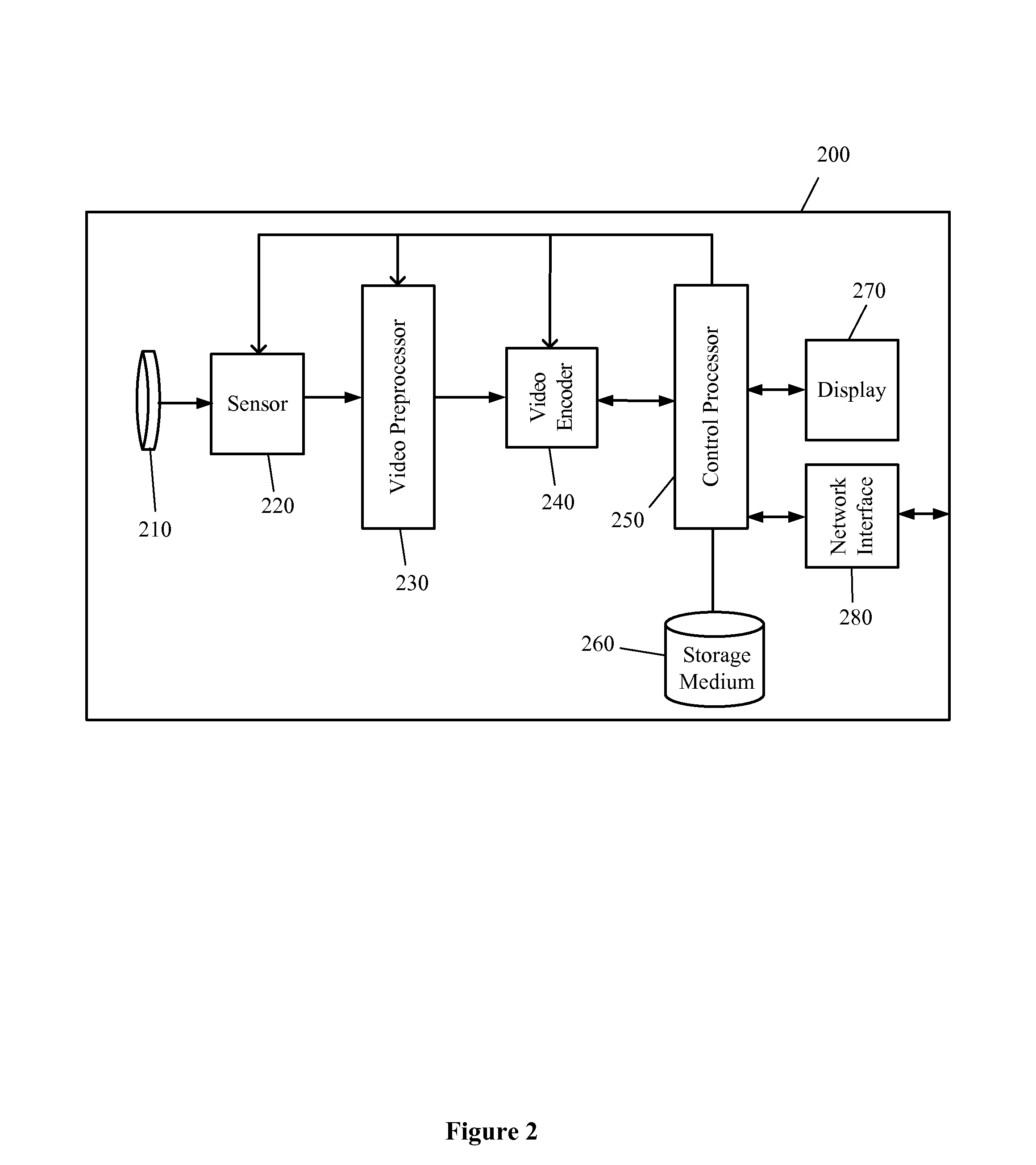
[0071]FIG. 4A illustrates a sensor 220 according to a Sensor 220 is a charge-coupled device, and includes a plurality of photoactive regions 222 (e.g., capacitors), a charge amplifier 224, and an analog to digital (A / D) converter 226. Photoactive regions 222 accumulate an electrical charge from impinging light during an exposure period, the electrical charge corresponding to a single analog image. The accumulated electrical charged are transferred to charge amplifier 224, which converts the electrical charges into electrical voltages. A / D converter 226 then samples the electrical voltages so as to generate a digital image. According to one embodiment, the electrical voltages are sampled more than once per analog image so as to generate more than one digital image corresponding to the single analog image. For example, 2, 3, or more digital images may be generated from an analog image. For another example, 3 digital images may be generated from 2 analog images. For yet another exampl...

second embodiment

[0072]FIG. 4B illustrates a sensor 220 according to a Sensor 220 includes a plurality of active pixel sensors 228 and an analog to digital (A / D) converter 229. Sensor 220 may be fabricated using, for example, a CMOS process. Active pixel sensors 228 each include a photodiode for integrating impinging light during an exposure period and providing an electrical voltage corresponding to the integrated light, the electrical voltage for the photodiodes corresponding to a single analog image. A / D converter 229 then samples the electrical voltages so as to generate a digital image. According to one embodiment, the electrical voltages are sampled more than once per analog image so as to generate more than one digital image corresponding to the single analog image. For example, 2, 3, or more digital images may be generated from an analog image. For another example, 3 digital images may be generated from 2 analog images. For yet another example, 30 or 60 digital images may be generated from ...


PUM


Abstract

Systems, apparatuses, and methods are provided for processing video. In one method, analog image information is acquired over an exposure period, and digital image information is generated from the analog image information at a frame period where the exposure period is greater than the frame period. In another method, stored characteristic information such as images of parties are compared to a received characteristic information. If there is a match, a communication link is established between the parties.

Description

CROSS-REFERENCES TO RELATED APPLICATIONS [0001]The present application claims the benefit under 35 USC §119(e) of U.S. Provisional Application No. 61 / 398,767 filed on Jul. 1, 2010, the full disclosure of which is incorporated herein by reference in its entirety for all purposes.BACKGROUND [0002]Embodiments of the present invention generally relate to video processing and, more particularly, to processing and encoding that improve on design constraints such as reducing the bandwidth required for video compression, and to utilizing video processing techniques to manage communication links between multiple parties.[0003]With the migration from analog to digital video (MPEG and follow on standards), there has been a continuous effort to reduce the bit rate required for a given picture quality level. As high definition (HD) video over the Internet has become more commonplace, the need for improved (e.g., lower bit rate) video encoding systems has risen. Although ATSC (broadcast video / off...

Claims


Application Information

Patent Timeline
IPC IPC(8): H04N7/14H04N5/217H04N5/228
CPCH04N19/172H04N19/46H04N19/85H04N19/186H04N19/117
Inventor GUERRERO, RODOLFO VARGAS
Owner VIBARE
Learn More