Holographic Image Display Systems

a technology of image display and display spot, which is applied in the field of holographic image display system, can solve the problem of not giving an accurate measurement of a wavefront in an unmodified system, and achieve the effects of flattening out phase distortion, and improving the signal-to-noise ratio

Inactive Publication Date: 2012-01-12
LIGHT BLUE OPTICS
View PDF6 Cites 68 Cited by
  • Summary
  • Abstract
  • Description
  • Claims
  • Application Information

AI Technical Summary

Benefits of technology

[0021]In some preferred implementations the patch on a wavefront sensing hologram is configured to define a phase ramp (that is, phases that vary linearly over the extent of the patch), albeit this may be quantised by the ability of the SLM to display such a ramp. This moves the target spot position away from the zero order spot (irrespective of whether a binary phase or multiphase SLM is employed), thus improving signal-to-noise ratio of the measurement of displayed spot position. Preferably the second portion of the hologram, in embodiments the remainder of the hologram apart from the patch, is configured to direct light generally towards a boundary of the image plane, for example towards one or more edges and / or corners of the image plane, again to help to improve signal-to-noise ratio.
[0031]The invention also provides a holographic image display system configured to implement a method as described above, in particular including means for driving the SLM to display a wavefront sensing hologram including a patch configured to direct light towards a target spot position in the image plane, and preferably to direct a remainder of the light away from the target spot. Preferably such a system also includes non-volatile memory to store a map of phase aberration corrections to be applied when displaying a wavefront sensing hologram, to facilitate multiple iterations of correction.
[0034]The skilled person will appreciate that the coherent light source need only be sufficiently coherent to be able to display a hologram. Thus satisfactory, albeit inferior, holograms can be displayed using a light emitting diode rather than a laser. In embodiments of the holographic image display system the diffuser can improve perceived image quality by reducing speckle, but can also introduce phase aberrations. Thus the above described techniques can be particularly advantageous in such a system. In embodiments the diffuser comprises a pixellated, quantised phase diffuser. Optionally the diffuser may be mechanically coupled to an actuator configured to dither the diffuser, in which case the phase aberration corrections may be mapped with or without the dither applied.

Problems solved by technology

It is known to employ a Shack-Hartmann sensor for measuring the phase of a wavefront, but to employ such a sensor in a holographic image display system would generally require modification of the system, which is undesirable and would not give an accurate measurement of a wavefront in an unmodified system.

Method used


Image

  • Holographic Image Display Systems
  • Holographic Image Display Systems
  • Holographic Image Display Systems

Examples


Embodiment Construction

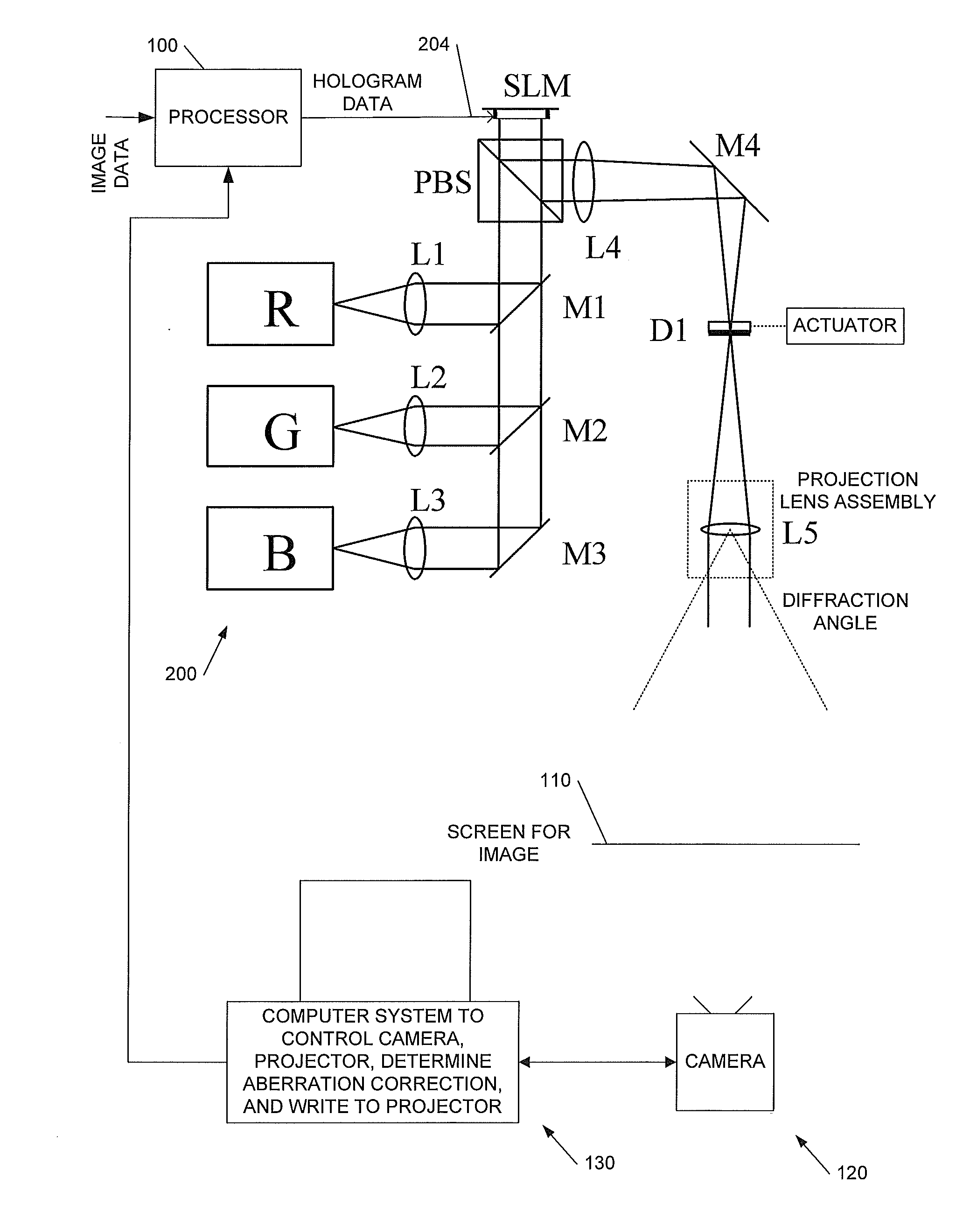
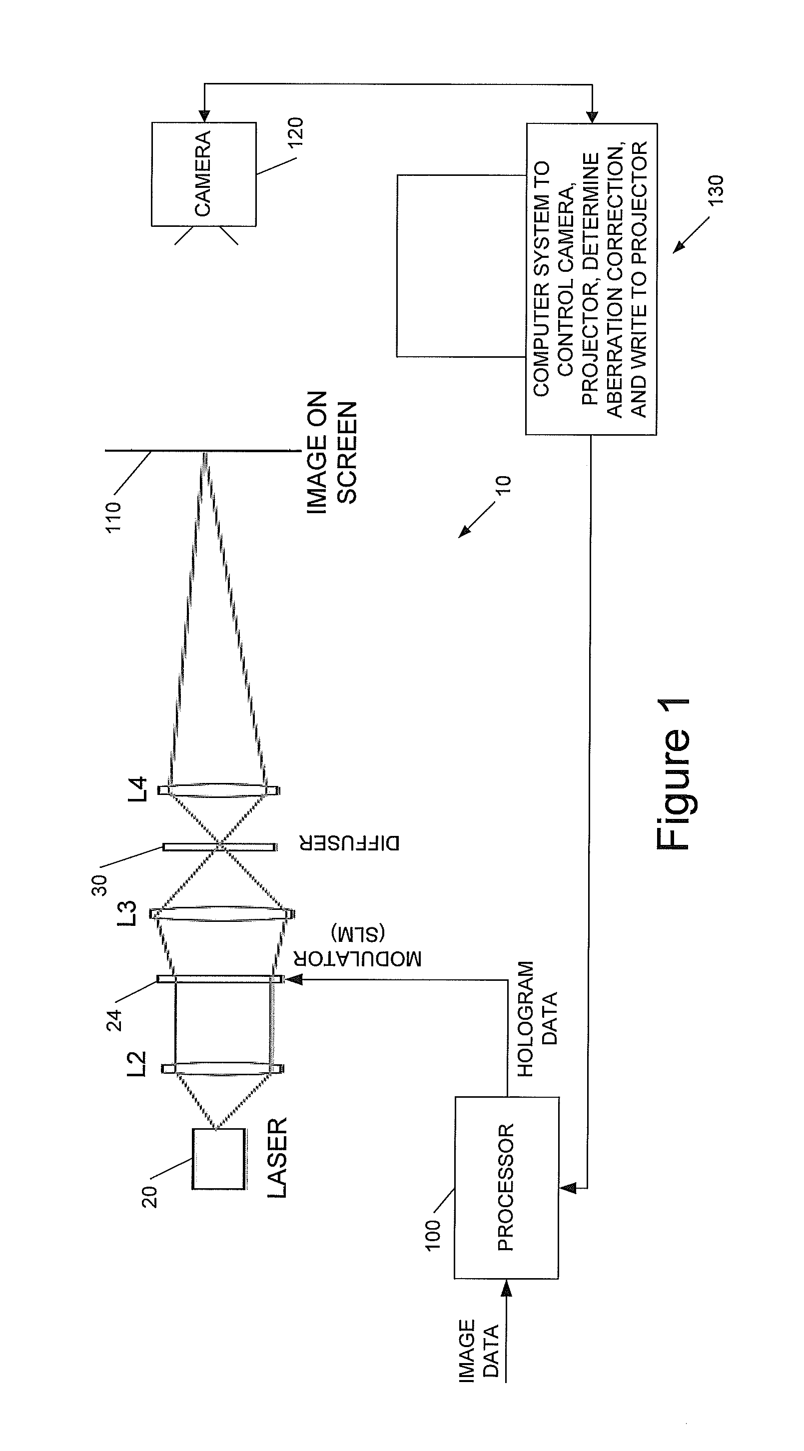
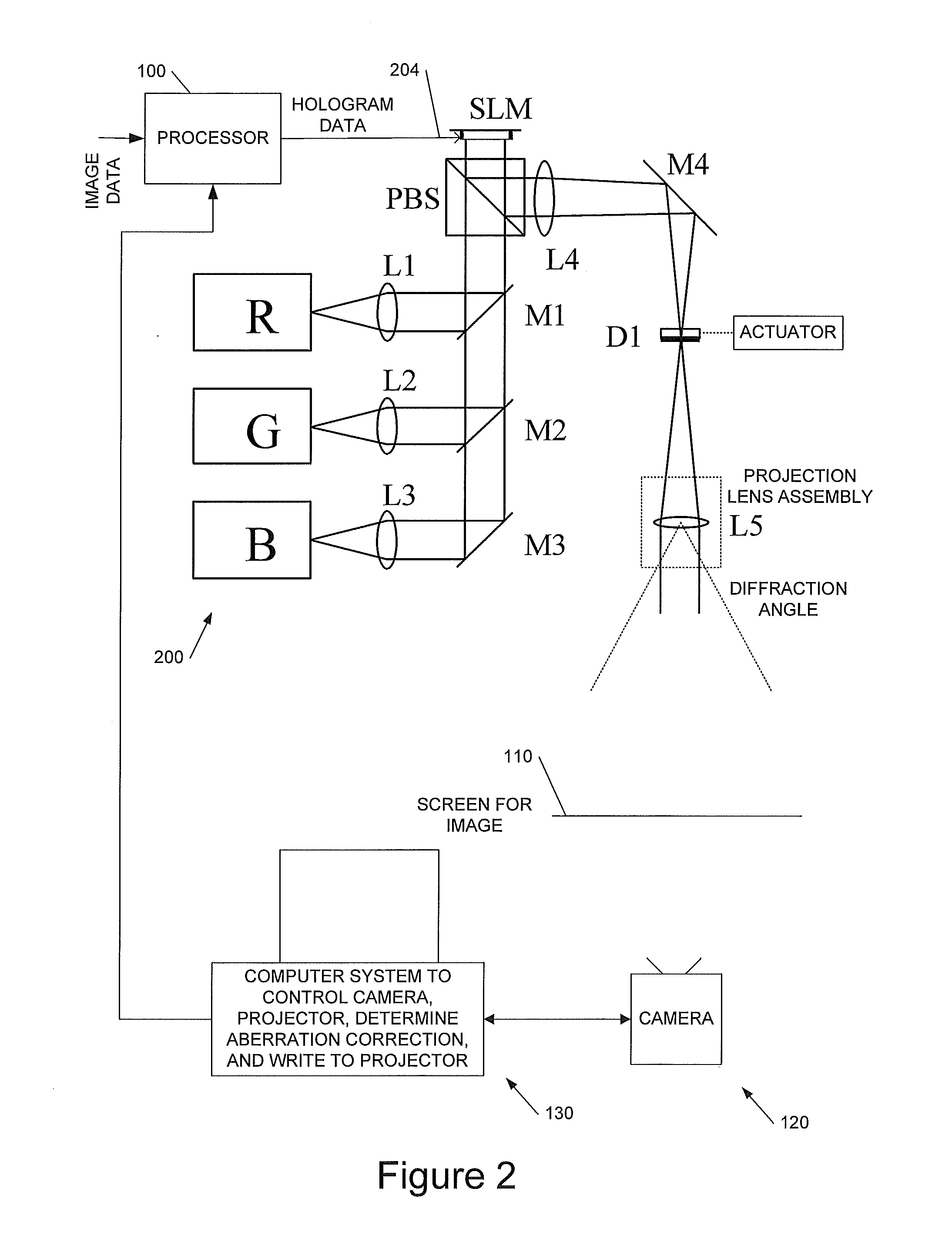
[0040]This invention relates to methods, apparatus and computer program code for aberration measurement and correction in holographic image projection systems, and to aberration-corrected holographic image projection systems.

[0041]We will describe a way of using the phase-modulating element in a diffractive, holographic projector to measure the aberrations present in the projector in such a way as to make it easy to correct for them. The approach measures the wavefront directly, but without requiring the introduction of any optical elements not already present in the system—the measurement can be carried out with an unmodified projector. In broad terms the technique identifies what happens to light incident on small patches of the SLM, and exploits the fact that average phase gradient there corresponds to a position offset in the resulting image.

[0042]To aid understanding of the invention we first describe some preferred implementations of holographic image display systems with whic...


PUM


Abstract

We describe a method of determining an aberration correction for a holographic image display system using a spatial light modulator (SLM) to display a hologram. Embodiments of the invention measure the corrections needed for a particular projection system, using the same system SLM as used to generate the images to provide wavefront-sensing holograms. The projector's projection optics are used to provide the wavefront sensor and there is no need for lenslets. Embodiments of the invention use a plurality of successive holograms directing light from differently-located patches on the hologram into the image.

Description

CROSS REFERENCE TO RELATED APPLICATION[0001]This application claims priority to PCT Application No. PCT / GB2010 / 050503 entitled “Holographic Image Display Systems” and filed Mar. 25, 2010, which itself claims priority to Great Britain Patent Application No. GB0905259.8 filed Mar. 27, 2009. The entirety of each of the aforementioned applications is incorporated herein by reference for all purposes.BACKGROUND OF THE INVENTION[0002]This invention relates to methods, apparatus and computer program code for aberration measurement and correction in holographic image projection systems, and to aberration-corrected holographic image projection systems.[0003]We have previously described techniques for displaying an image holographically—see, for example, WO 2005 / 059660 (Noise Suppression Using One Step Phase Retrieval), WO 2006 / 134398 (Hardware for OSPR), WO 2007 / 031797 (Adaptive Noise Cancellation Techniques), WO 2007 / 110668 (Lens Encoding), WO 2007 / 141567 (Colour Image Display), and WO 2008...

Claims


Application Information

Patent Timeline
Patent Type & Authority Applications(United States)
IPC IPC(8): G03H1/08
CPCG03H1/08G03H1/2294G03H2001/2247G03H2001/2218G03H2001/2244G03H2001/0491G03H1/32G03H2001/0825G03H2223/14G03H1/22H04N5/7416
Inventor CABLE, ADRIAN J.MCCAUGHAN, GARETH J.
Owner LIGHT BLUE OPTICS
Why Eureka
Try Eureka