Image forming apparatus

a technology of image forming apparatus and forming apparatus, which is applied in the direction of electrographic process apparatus, instruments, optics, etc., can solve the problems of density fluctuation and improper transfer, and achieve the effect of preventing stop (rotation), preventing positional deviation of electrostatic latent image and improper transfer

Inactive Publication Date: 2012-01-12
CANON KK
View PDF6 Cites 25 Cited by
  • Summary
  • Abstract
  • Description
  • Claims
  • Application Information

AI Technical Summary

Benefits of technology

[0007]A principal object of the present invention is to provide an image forming apparatus capable of suppressing positional deviation of an electrostatic latent image and improper transfer by avoiding agglomeration of a residual matter in a nip area at an image bearing member surface due to contact pressure of a cleaning blade.
[0008]Another object of the present invention is to provide an image forming apparatus capable of preventing stop of (rotation of) the image bearing member in a state in which unnecessary toner is transferred from a developing device onto the image bearing member, during cleaning blade contact pressure control, without being removed from the image bearing member surface.
[0009]A further, object of the present invention is to provide an image forming apparatus capable of suppressing scattering of the unnecessary toner inside the image forming apparatus to prevent contamination of the inside of the image forming apparatus with scattered toner.

Problems solved by technology

Further, at a portion where a toner image formed on the image bearing member is transferred onto a transfer material, a speed of the image bearing member relative to the transfer material is changed depending on the fluctuation in speed, so that improper transfer such as density fluctuation or the like of the toner image to be transferred onto the transfer material occurs.

Method used


Image

  • Image forming apparatus
  • Image forming apparatus
  • Image forming apparatus

Examples


embodiment 1

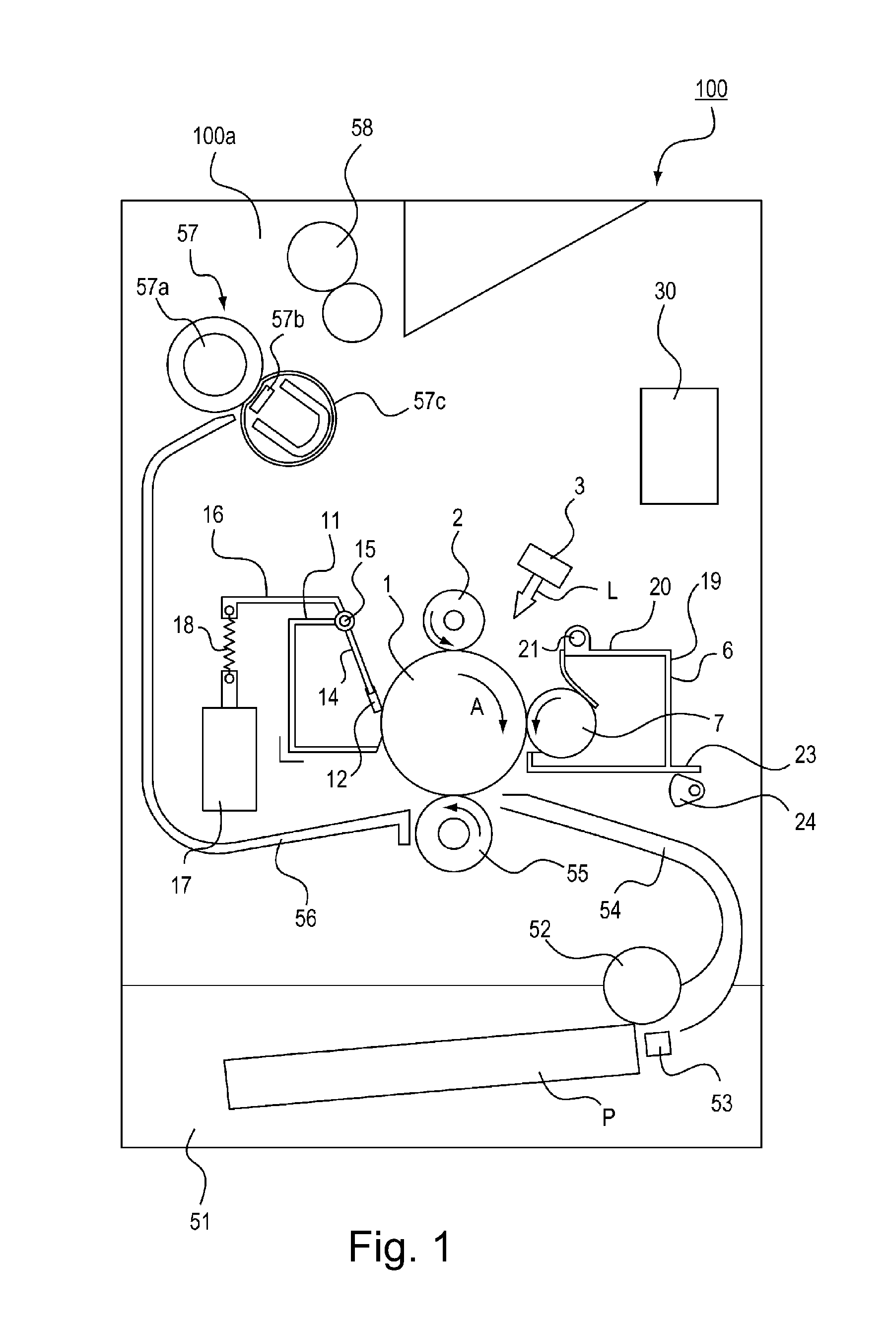
[0017]An embodiment of the image forming apparatus according to the present invention will be described with reference to the drawings. FIG. 1 is a structural view of an image forming apparatus 100 in this embodiment. As shown in FIG. 1, the image forming apparatus 100 includes an apparatus main assembly 100a communicatably connected with an external device such as a personal computer. Further, depending on image information from the external device, an image is formed on a recording material P (such as recording paper, OHP sheet or cloth) with a developer by an electrophotographic image forming process.

[0018]A photosensitive drum (image bearing member) 1 is uniformly charged to a negative potential of −600 V by a charging roller 2. The photosensitive drum 1 is irradiated with laser light L from an exposure device 3 depending on the image information to lower the negative potential to about −100 V at an exposed portion, so that an electrostatic latent image is formed. The electrosta...

embodiment 2

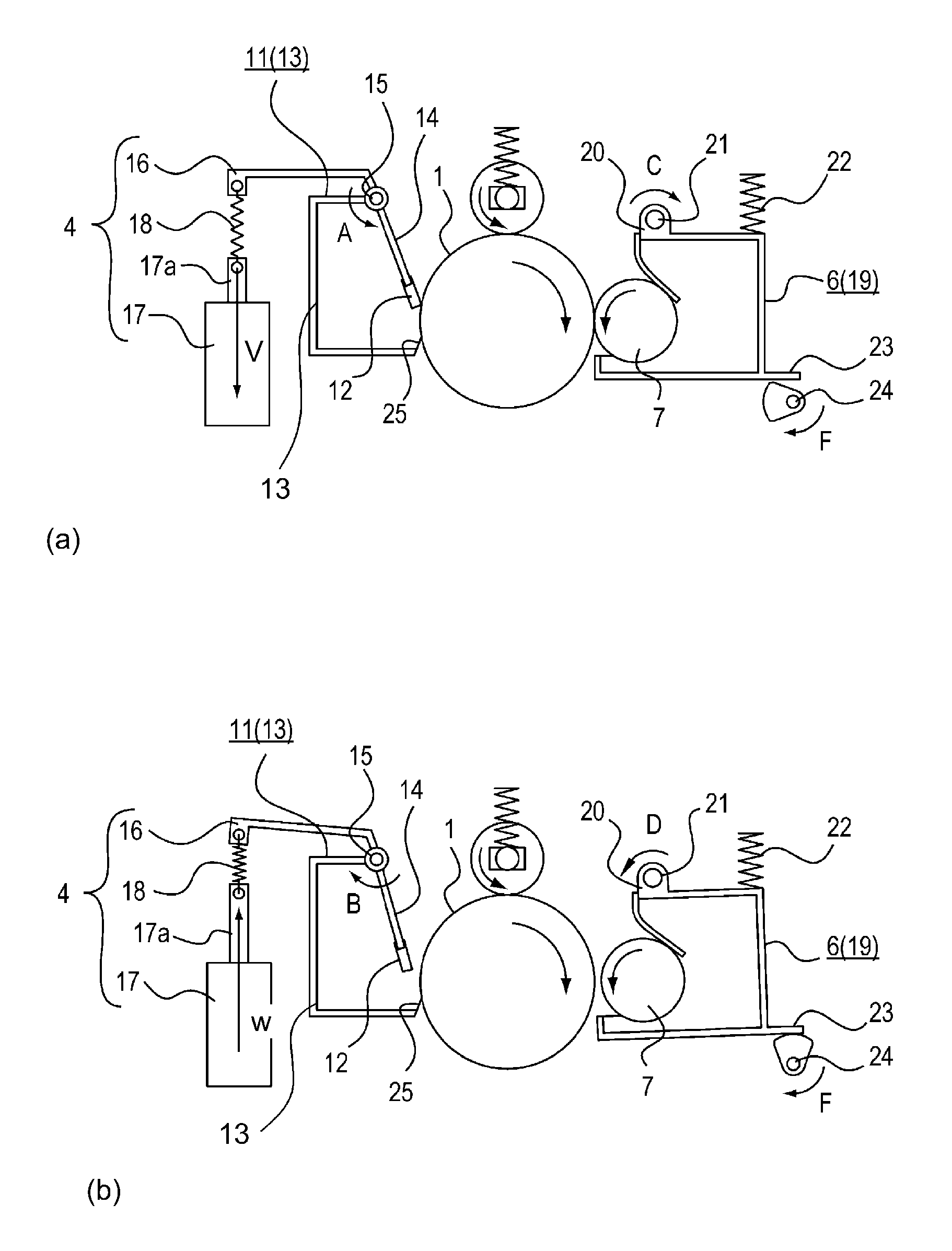
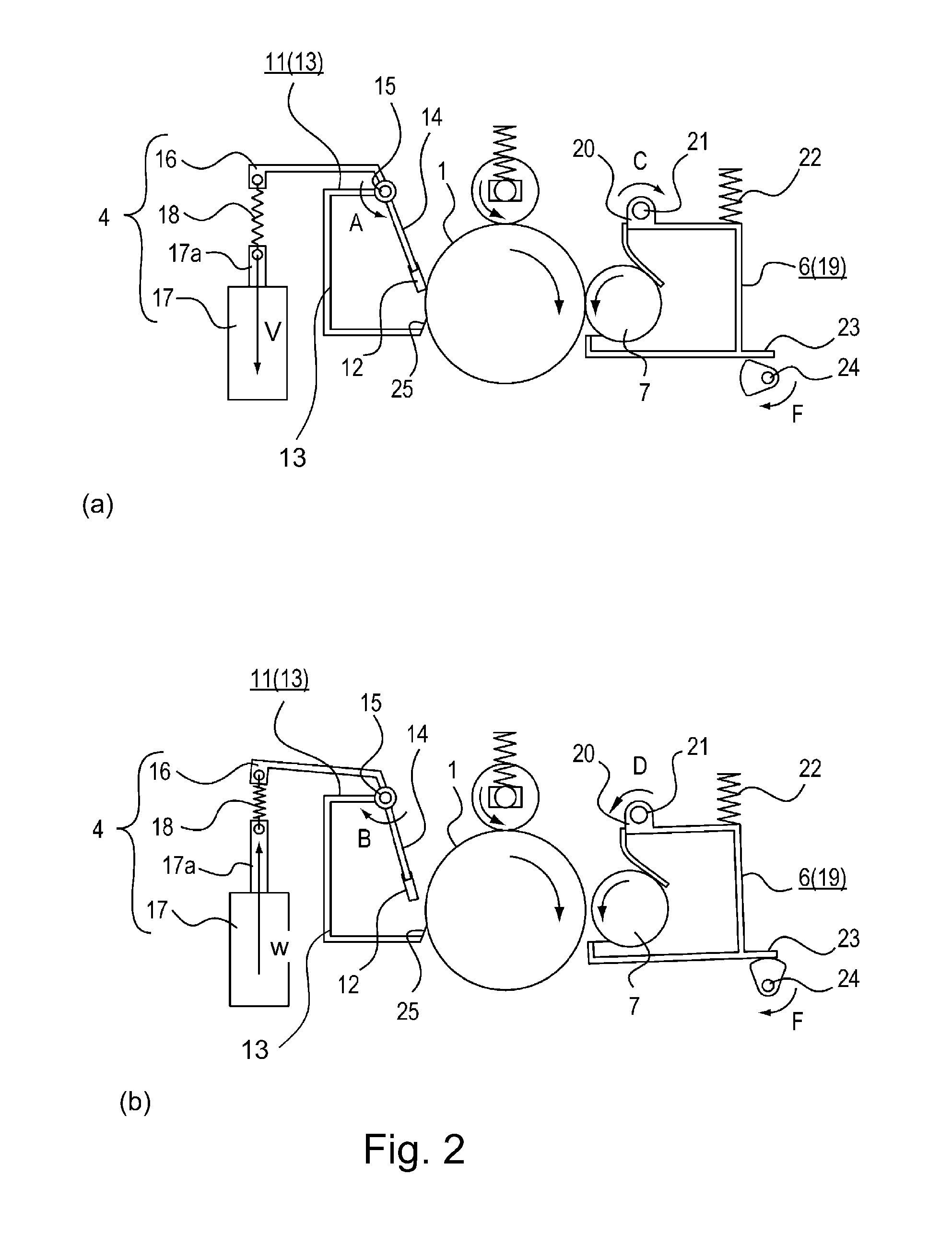
[0056]Next, a cleaning blade 112 supporting constitution of a cleaning device 111 and a contact load adjusting constitution of the cleaning blade 111 with respect to the photosensitive drum 1 will be described with reference to FIGS. 5 and 6.

[0057]A difference of a constitution of Embodiment 2 from that of Embodiment 1 is that the constitution of the mechanism for adjusting the contact load of the cleaning blade 112 on the photosensitive drum 1 is different from that in Embodiment 1. That is, the constitution of Embodiment 2 is, particularly, characterized by constitutions of the cleaning blade 112, a blade holder 114, a cleaning device frame 113 and coil springs 118 (118a, 118b). In this embodiment, a holding mechanism for holding the cleaning blade 112 so that a contact pressure of the cleaning blade 112 applied to the photosensitive drum 1 when the photosensitive drum 1 is rotated is larger than that when the rotation of the photosensitive drum 1 is stopped is provided. The holdi...


PUM


Abstract

An image forming apparatus includes a rotatable image bearing member; a cleaning blade for removing toner in contact with the image bearing member; a load adjusting device for adjusting a contact load between the cleaning blade and the image bearing member; a developing roller for developing an electrostatic latent image on the image bearing member; a developing roller moving device for moving the developing roller between a developing position in which the electrostatic latent image is to be developed and a non-developing position retracted from the developing position; and a control device for effecting control such that the developing roller is moved from the developing position to the non-developing position by the developing roller moving device during rotation of the image bearing member and after an area on the image bearing member opposed to the developing roller at the time when the developing roller is started to be moved from the developing position to the non-developing position passes through a contact area between the cleaning blade and the image bearing member, the contact load is made smaller than that during development by the load adjusting device and then the rotation of the image bearing member is stopped.

Description

FIELD OF THE INVENTION AND RELATED ART[0001]The present invention relates to an image forming apparatus such as a copying machine.[0002]In a conventional image forming apparatus, transfer residual toner is scraped and removed from an image bearing member by using a cleaning blade having flexibility (rubber elasticity). The cleaning blade is contacted to the image bearing member, in order to improve a cleaning efficiency, counterdirectionally with a rotational direction of the image bearing member during image formation (Japanese Laid-Open Patent Application (JP-A) Hei 8-166751).[0003]In this image forming apparatus, during rest of the image forming apparatus (during stop of rotation of the image bearing member), a residual matter with a small particle size, such as fine powdery toner or an external additive, which remains in a cleaning blade contact area of the image bearing member (in a nip area) is pressed against the surface of the image bearing member with a press-contact force....

Claims


Application Information

Patent Timeline
Patent Type & Authority Applications(United States)
IPC IPC(8): G03G15/00G03G21/00
CPCG03G15/0806G03G2221/1618G03G21/0029G03G2221/1654G03G2221/163
Inventor KAWAI, TACHIOSUZUKI, TATSUYAKAKUTA, HIDEKI
Owner CANON KK
Why Eureka
Try Eureka