
Closed-loop control of cmp slurry flow

a closed-loop control and slurry technology, applied in the direction of grinding machine components, manufacturing tools, lapping machines, etc., can solve the problems of polishing pad efficiency change, polishing pad eventually needs replacement, etc., and achieve the effect of reducing the thickness of the polishing pad

Inactive Publication Date: 2012-01-12
APPLIED MATERIALS INC
View PDF9 Cites 7 Cited by
  • Summary
  • Abstract
  • Description
  • Claims
  • Application Information

AI Technical Summary

Benefits of technology

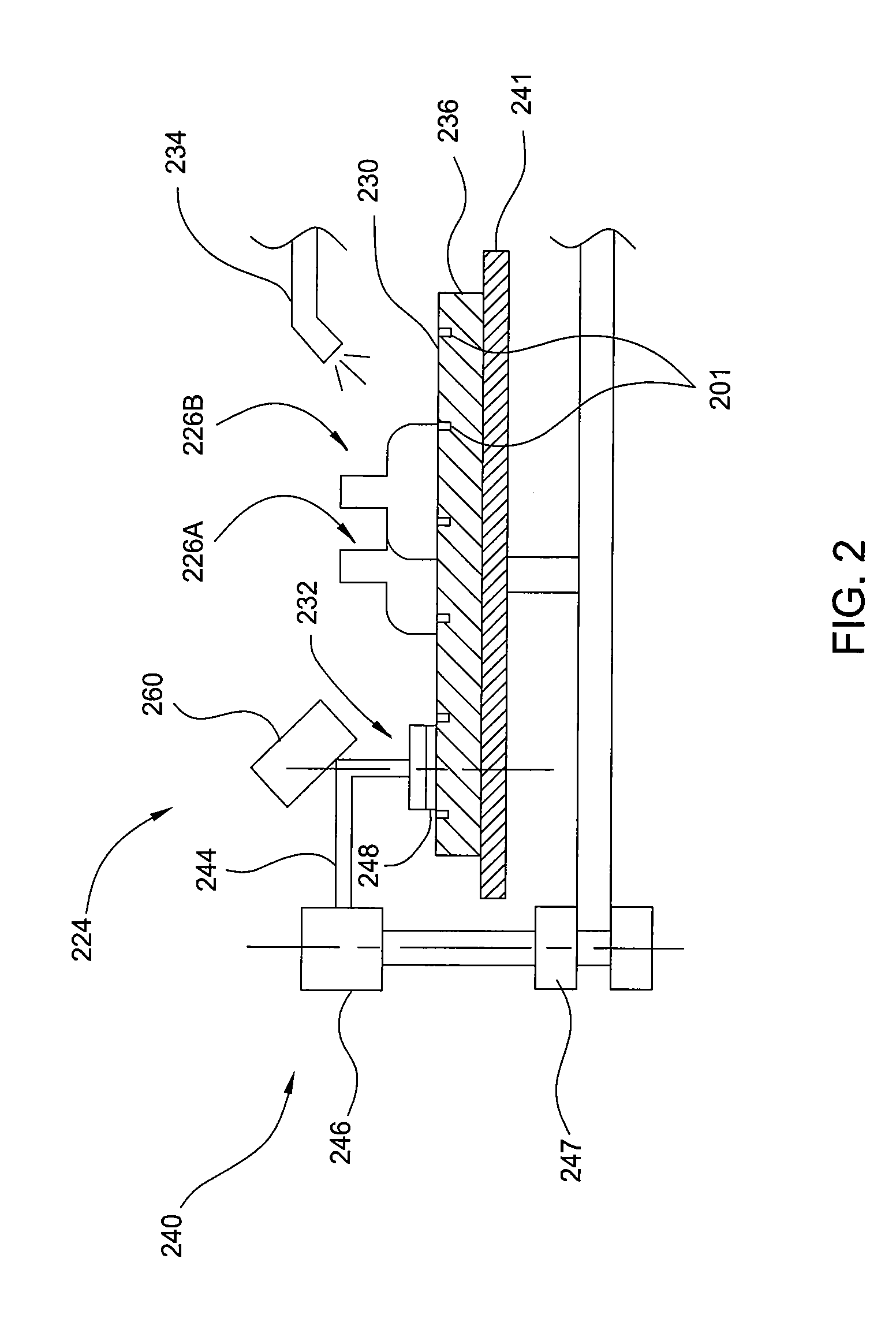
[0008]In another embodiment, a method includes measuring a thickness of a polishing pad having grooves disposed in a polishing surface of the polishing pad. The measured thickness of the polishing pad is compared to an initial pre-polish thickness of the polishing pad to determine a reduction in the polishing pad thickness. A depth of the grooves disposed in the polishing surface is then calculated. A flow rate of a polishing slurry introduced to the polishing surface is adjusted in response to the calculated depth of the grooves disposed in the polishing surface. A predetermined number of substrates are then polished. The polishing comprises contacting each of the predetermined number of substrates to the polishing pad, and introducing the polishing slurry to the polishing pad at the adjusted flow rate for each of the predetermined number of substrates. The method is then repeated.

Problems solved by technology

However, as more substrates are polished in the CMP apparatus the efficiency of the polishing pad changes, and the polishing pad eventually requires replacement.

Method used


Image

  • Closed-loop control of cmp slurry flow
  • Closed-loop control of cmp slurry flow
  • Closed-loop control of cmp slurry flow

Examples


Embodiment Construction

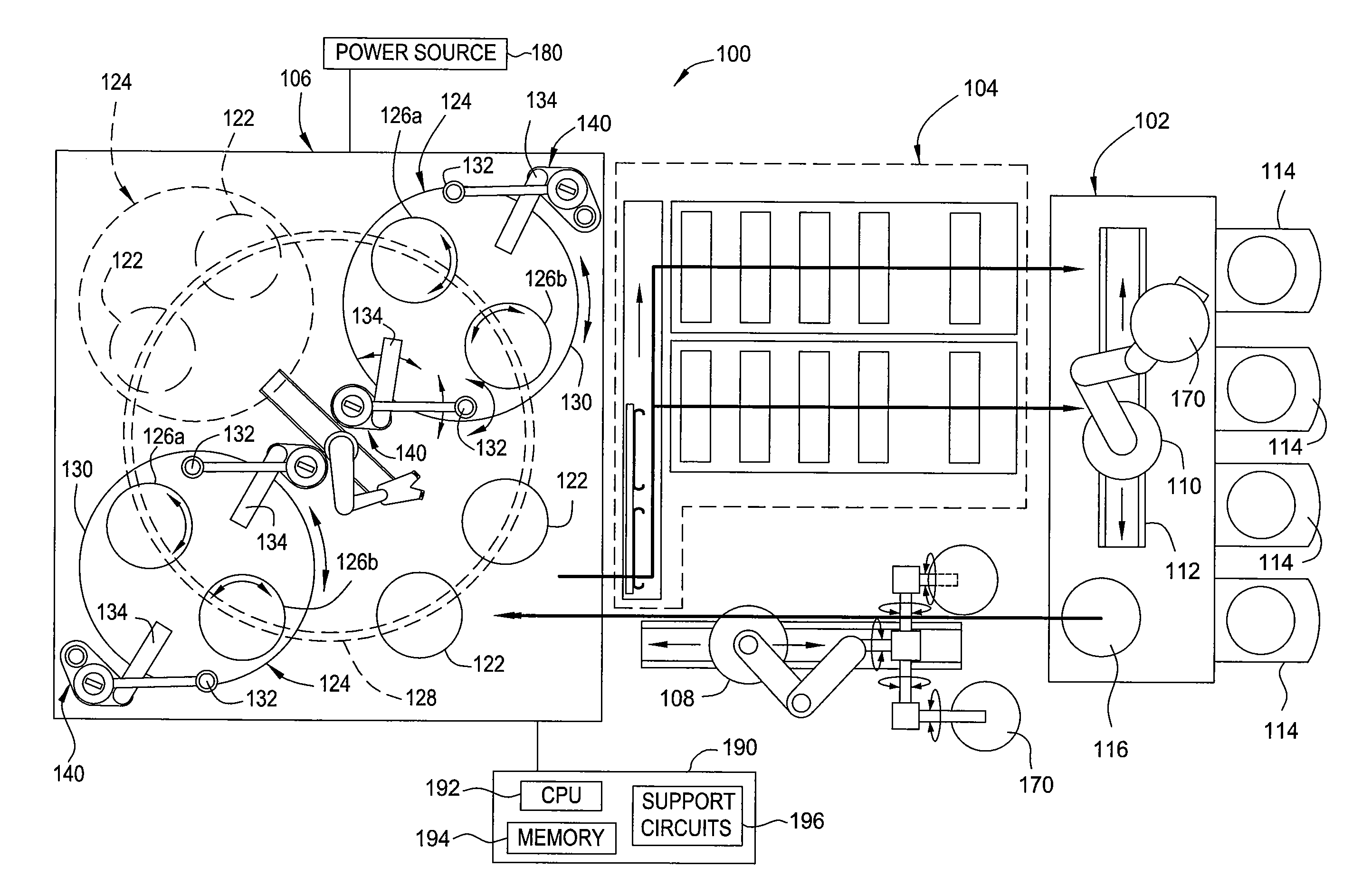
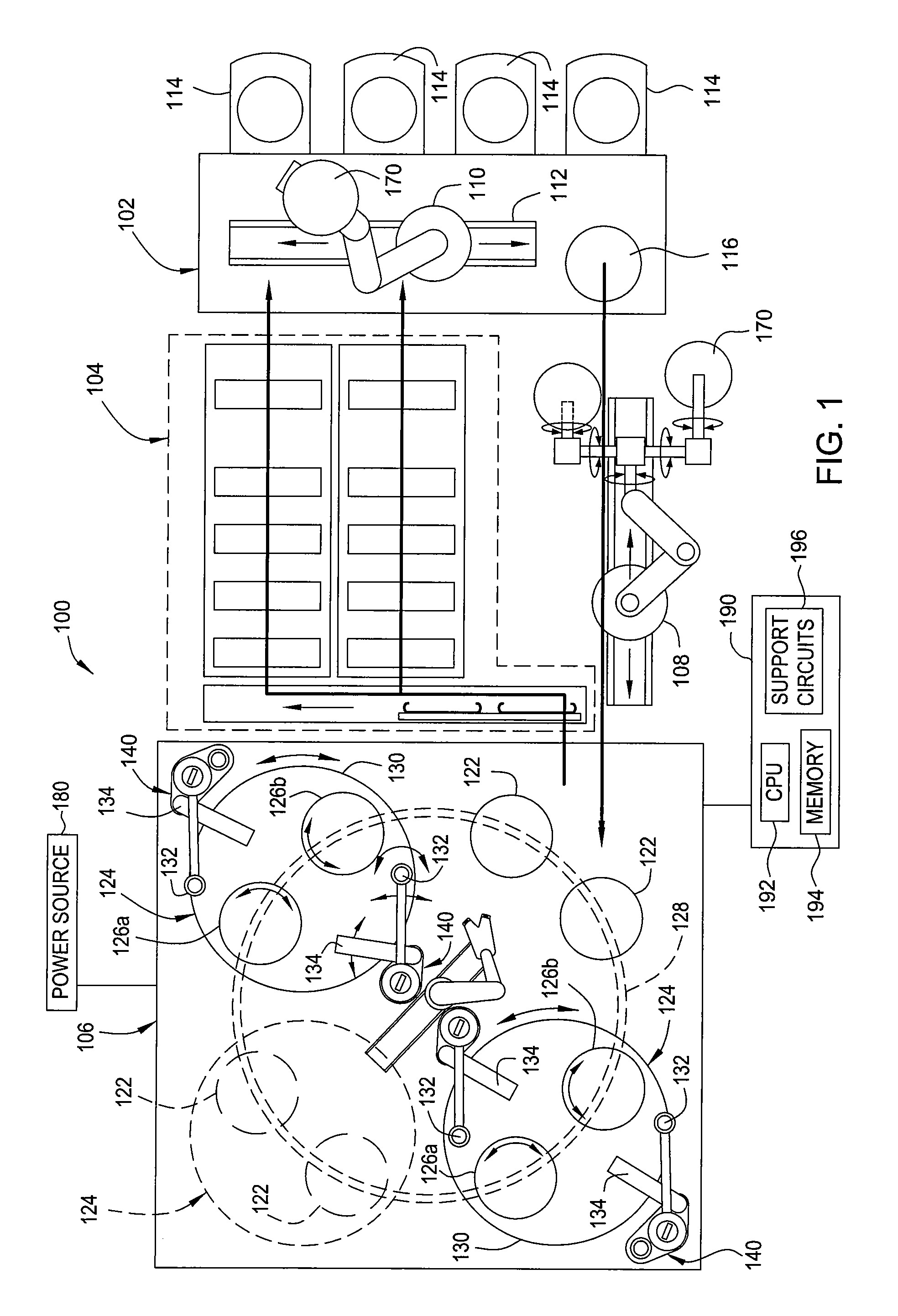
[0018]Embodiments of the present invention generally relate to methods for chemical mechanical polishing a substrate. The methods generally include measuring the thickness of a polishing pad having grooves or other slurry transport features on a polishing surface. Once the depth of the grooves on the polishing surface is determined, a flow rate of a polishing slurry is adjusted in response to the determined groove depth. A predetermined number of substrates are polished on the polishing surface. The method can then optionally be repeated.

[0019]While the particular apparatus in which the embodiments described herein can be practiced is not limited, it is particularly beneficial to practice the embodiments in a REFLEXION GT™ system, REFLEXION® LK CMP system, and MIRRA MESA® system sold by Applied Materials, Inc., of Santa Clara, Calif. Additionally, CMP systems available from other manufacturers may also benefit from embodiments described herein.

[0020]FIG. 1 is a top schematic view il...


PUM


Abstract

Embodiments of the present invention generally relate to methods for chemical mechanical polishing a substrate. The methods generally include measuring the thickness of a polishing pad having grooves or other slurry transport features on a polishing surface. Once the depth of the grooves on the polishing surface is determined, a flow rate of a polishing slurry is adjusted in response to the determined groove depth. A predetermined number of substrates are polished on the polishing surface. The method can then optionally be repeated.

Description

BACKGROUND OF THE INVENTION[0001]1. Field of the Invention[0002]Embodiments of the present invention generally relate to methods of chemical mechanical polishing a substrate.[0003]2. Description of the Related Art[0004]Chemical mechanical polishing (CMP) is a common technique used to planarize substrates. CMP utilizes two modes to planarize substrates. One mode is a chemical reaction using a chemical composition, typically a slurry or other fluid medium, for removal of material from substrates, and the other is mechanical force. In conventional CMP techniques, a substrate carrier or polishing head is mounted on a carrier assembly and positioned in contact with a polishing pad in a CMP apparatus. The carrier assembly provides a controllable pressure to the substrate urging the substrate against the polishing pad. The pad is moved relative to the substrate by an external driving force. Thus, the CMP apparatus affects a polishing or rubbing movement between the substrate surface and th...

Claims


Application Information

Patent Timeline
Patent Type & Authority Applications(United States)
IPC IPC(8): B24B49/10
CPCB24B37/005B24B57/02B24B37/26B24B37/042H01L21/304
Inventor MENK, GREGORY E.TSAI, STAN D.CHO, SANG J.DHANDAPANI, SIVAKUMAR
Owner APPLIED MATERIALS INC
Learn More