[0010]The inventor has found it is advantageous to provide a method, device and
system that permit an angle between a disc implant and
insertion instrument to be altered without removing the implant from the intervertebral space. This new
surgical approach also removes the native disc contents from a generally lateral direction, which permits the peritoneal contents to fall out of the surgical field, while also taking
advantage of the
mechanics of anterior interbody
surgery.
[0012]In one embodiment, an implant is positioned in the
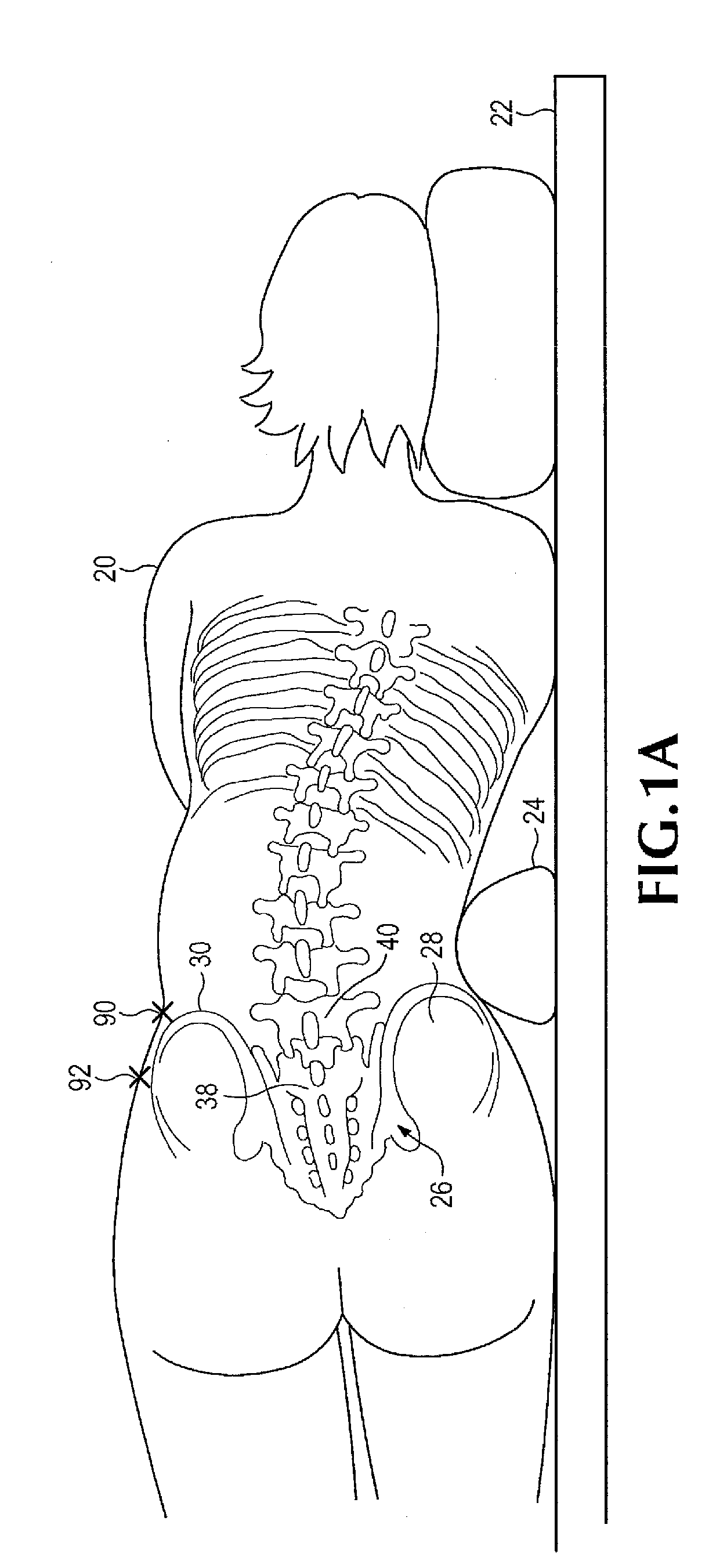
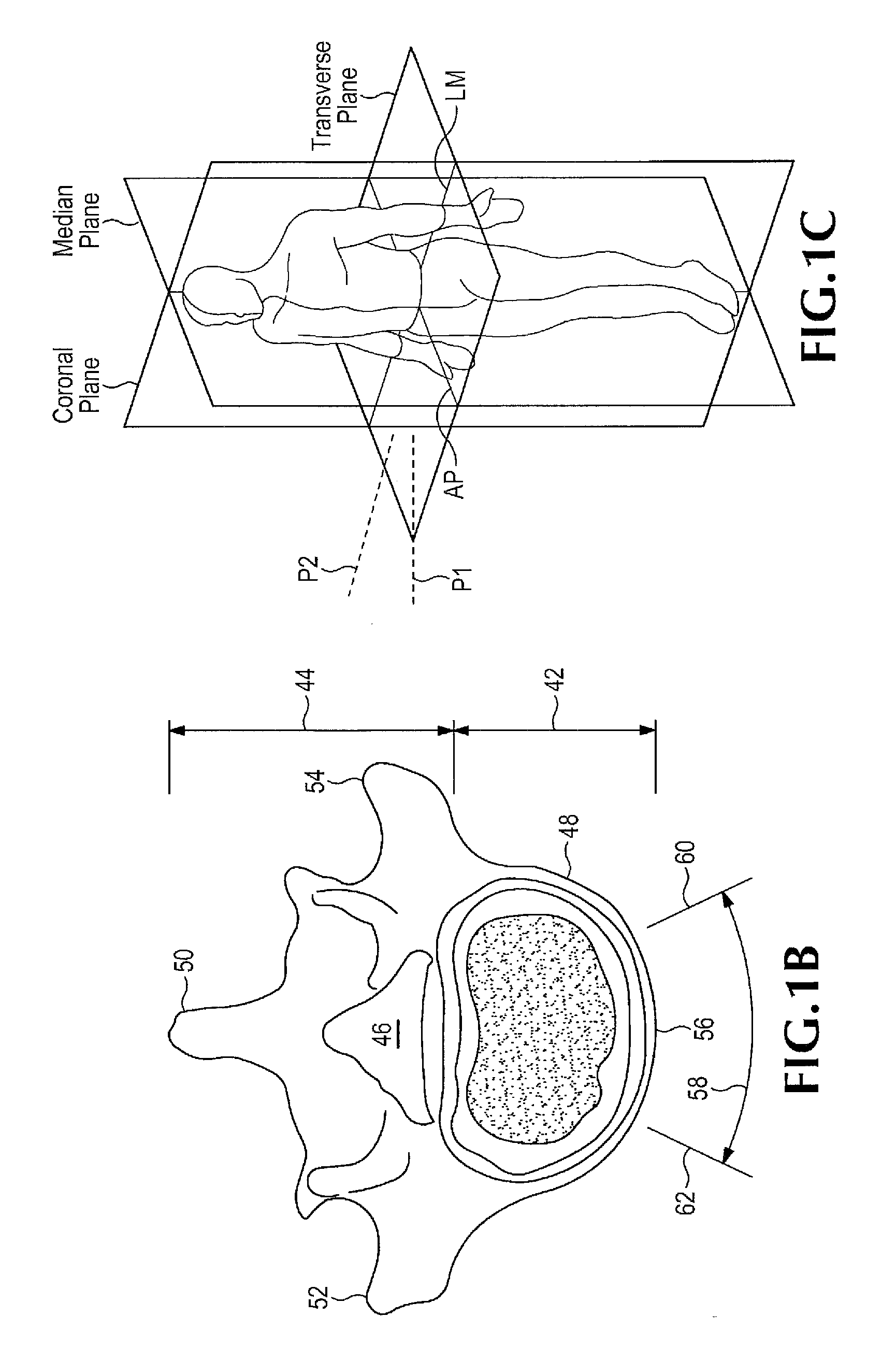
intervertebral disc space of a laterally positioned subject by accessing the anterior face of the spinal disc intervertebral space, between the L5 and S 1 vertebrae, from an anterolateral retroperitoneal approach. An oblique operative corridor is then established to the anterior face of the spinal disc space by introducing a
retractor instrument anterolaterally to the spinal disc space, for example anterior to the
anterior superior iliac spine, and in some instances between the level of the anterior superior iliac spine and the anterior inferior iliac spine. The spinal disc contents are removed from the intervertebral space through the operative corridor, and an elongated implant is introduced through the operative corridor into the intervertebral space diagonally (at an angle). The elongated implant is then pivoted within the intervertebral space to eventually position the implant substantially medial-laterally within the intervertebral space and achieve midline symmetric distribution of the
mechanical load on the implant. The ability to pivot the implant within the intervertebral space permits the elongated implant to be generally aligned with the
insertion instrument and advanced into the body through a relatively narrow operative corridor, then turned to its final position within the intervertebral space.
[0015]In some disclosed embodiments, the implant is an elongated elastomeric member that has a top bearing face, a bottom bearing face, a front face, a rear face, an ipsilateral face and a contralateral face. The rear face of the implant may be substantially flat. The contralateral face of the implant may be rounded (particularly at its corners that adjoin the front and rear faces) to minimize trauma induced by advancing the implant diagonally into the intervertebral space at the
oblique angle, and using the ipsilateral face to function as an
impact hinge or pivot point as the implant is moved in one or more realignments from the oblique to medial-lateral orientation. The ipsilateral end of the implant may have a pivot axis and an interface element, such as multiple pairs of spaced docking holes arranged on a curved surface that extends partially circumferentially around the pivot axis. The selected pairs of spaced docking holes are positioned to mate with the docking element of the introducer instrument, such as a pair of docking pins that extend from a distal tip of the introducer instrument.
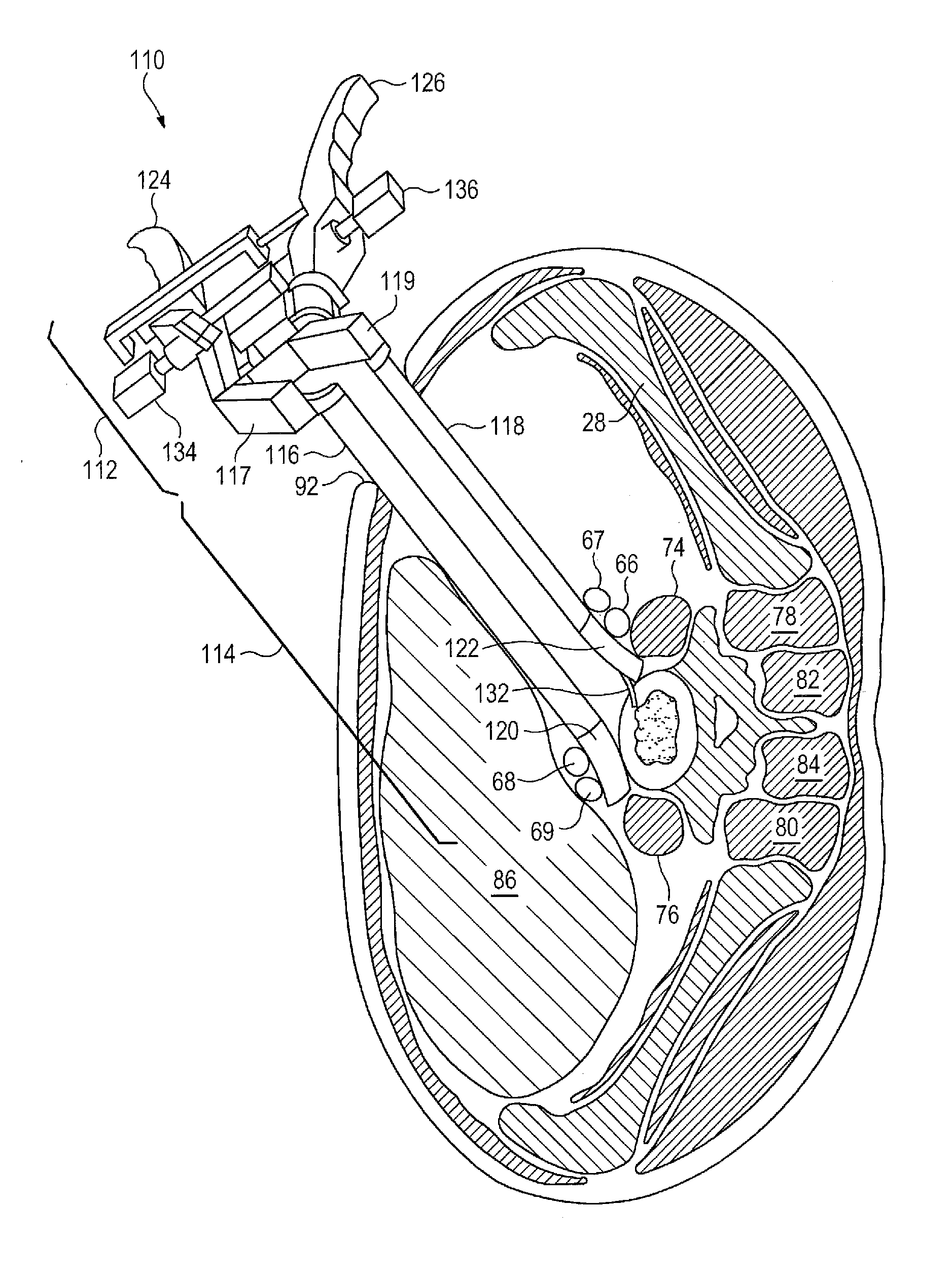
[0017]The retractor instrument may also take a variety of forms, but certain disclosed embodiments have an ipsilateral arm that is shorter than the contralateral arm. A
retractor blade on the ipsilateral arm therefore extends a shorter distance from the
handle than the
retractor blade on the contralateral arm. This asymmetric arrangement permits the retractor instrument to be advanced diagonally through the body from an anterolateral entrance point through the
abdominal wall to the anterior aspect of the
vertebral body. Since the contralateral arm is longer than the ipsilateral arm, the retractor blades at the anterior
vertebral body span the anterior face of the vertebral body, for example from the 10 o'
clock to 2 o'
clock positions. The retractor blades may be curved outwardly from a longitudinal axis of the retractor instrument to help minimize damage to the blood vessels as they are retracted. A thin shim with a tapered tip may be inserted into the intervertebral space and mounted to the ipsilateral blade to retain the instrument in its desired
angular orientation and distract adjacent vertebral bodies (such as L5 and S1) apart from one another during the procedure. The shim curves inwardly into the disc space, toward the midline of the body, away from the ipsilateral
retractor blade, and toward a longitudinal axis of the retractor instrument. The shim has a height sufficient to maintain the adjacent vertebral bodies spaced from one another while a trial spacer and subsequent disc implant are pivoted into place within the disc space. The present disclosure also includes a
system for positioning an implant in an intervertebral space of a subject. In certain disclosed embodiments, the
system includes the retractor instrument for establishing an operative corridor to the anterior face of the intervertebral space. The retractor instrument has a proximal
handle portion and a distal retractor blade portion that includes opposing ipsilateral and contralateral arms that are movable toward and away from one another to define a portion of the operative corridor therebetween. In certain embodiments, the ipsilateral retractor blade is carried by the ipsilateral arm, and a contralateral vascular retractor blade is carried by the contralateral arm. The contralateral arm and blade are longer than the ipsilateral arm and blade so that the retractor instrument can be introduced at an
oblique angle with the two retractor blades spaced apart on the anterior aspect of the vertebral body.

