Adhesion Enhanced Insulated Framing Member
a framing member and enhanced technology, applied in the direction of girders, joists, trusses, etc., can solve the problems of layered material pulling apart or delaminating, low beneficial insulation characteristics of thermal bridges, adhesion under stress, etc., and achieve the effect of resisting delamination
- Summary
- Abstract
- Description
- Claims
- Application Information
AI Technical Summary
Benefits of technology
Problems solved by technology
Method used
Image
Examples
example 1
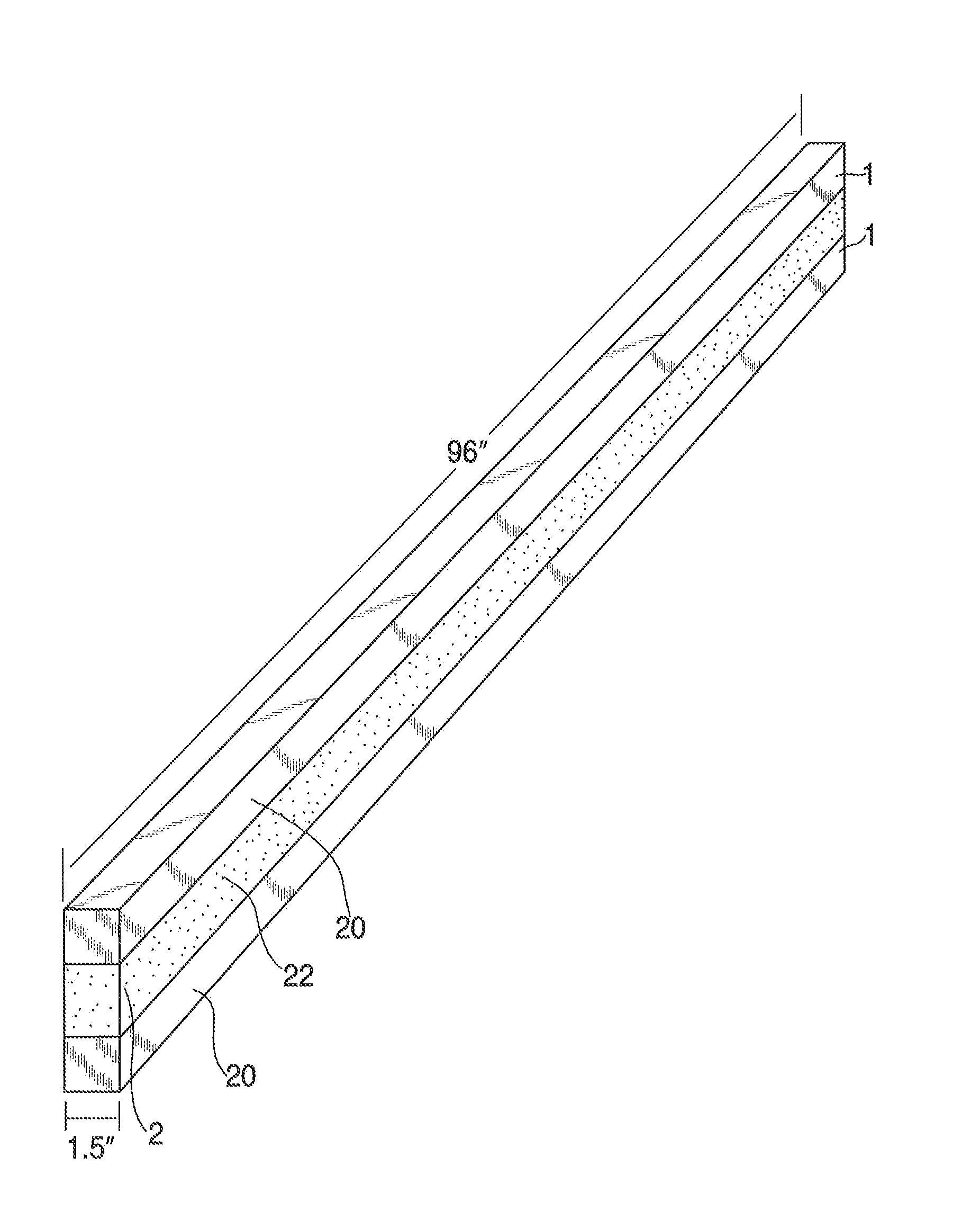
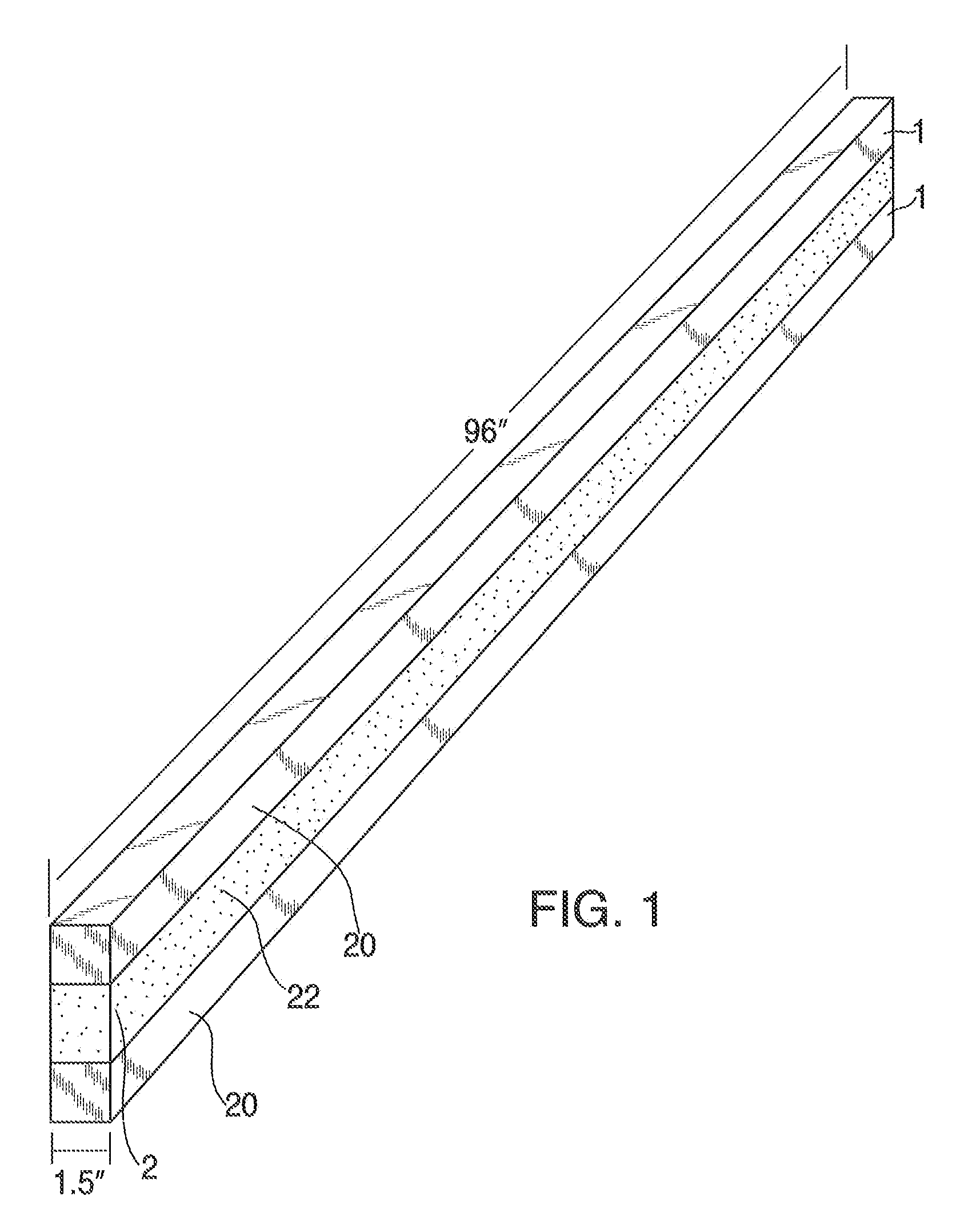
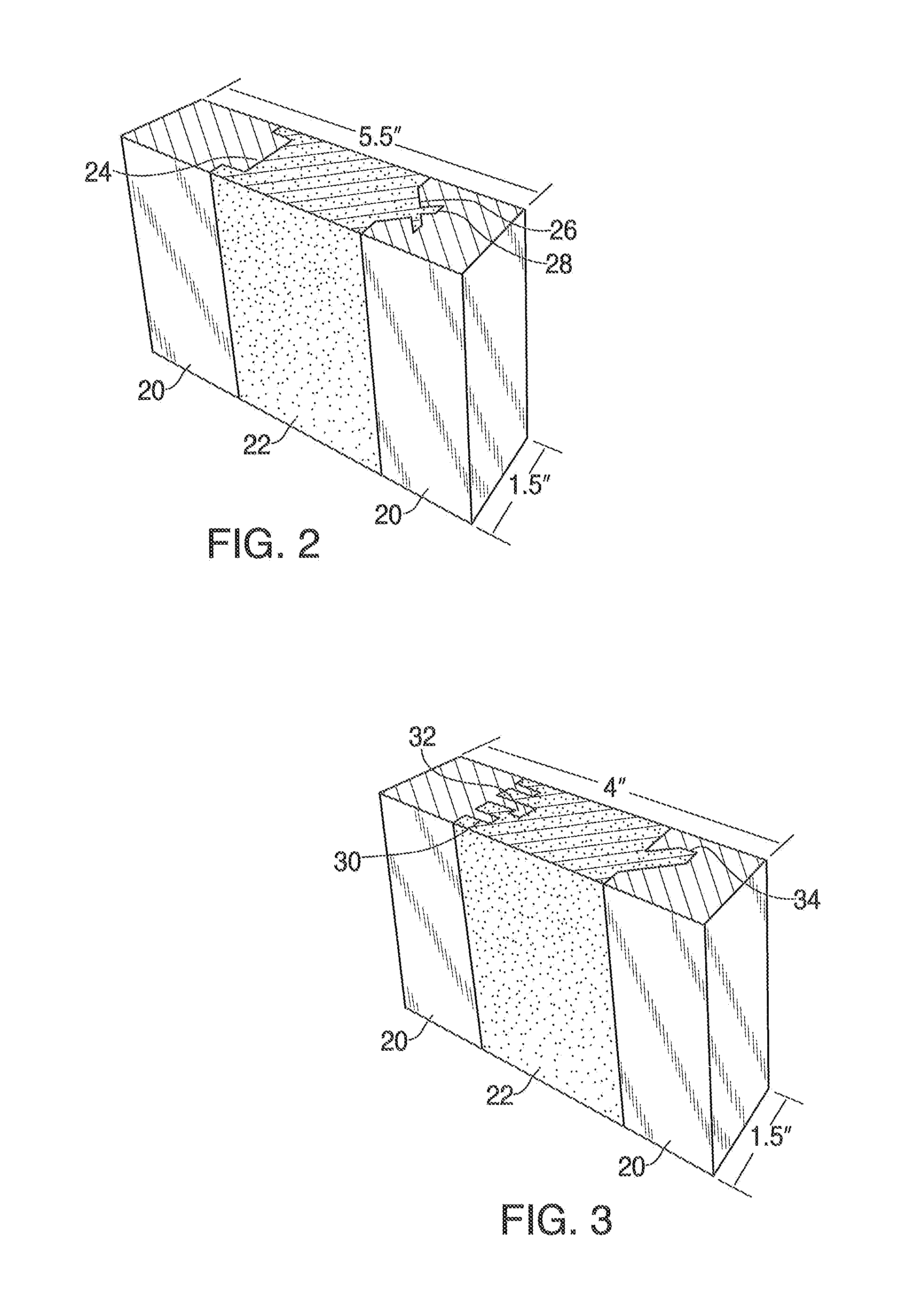
[0035]An enhanced adhesion framing element is prepared cut cutting 12.7 mm deep dovetails into 2 pieces of laminated veneer lumber. The two pieces of laminated veneer lumber are held 76 mm apart, with the dovetail surfaces facing each other. A polyurethane rigid foam insulation (SWD 4 pound rigid foam) is poured in the cavity and allowed to rise and fill the cavity including the dovetails. The foam density was measured at 106 kg / m3. After the foam was cured, the enhanced adhesion framing element was cut into pieces about 38 mm wide, to serve as a replacement for 2×6 structural lumber.
[0036]Samples were prepared and tested per ASTM D 1623, tensile strength. These samples were so that the lumber is on both ends of the specimen and polyurethane rigid foam insulation is in the center. The lumber and polyurethane interface has to bear the entire tensile load. The samples show failure deep in the foam layer near the dovetail. However, in the substantially planar region of the lumber, the ...
example 2
[0037]An enhanced adhesion framing element is prepared cut cutting 12.7 mm deep dovetails into 2 pieces of laminated veneer lumber. The two pieces of laminated veneer lumber are held 76 mm apart, with the dovetail surfaces facing each other. A polyurethane rigid foam insulation (SWD 4 pound rigid foam)is poured in the cavity and allowed to rise and fill the cavity including the dovetails. The foam density was measured at 106 kg / m3. After the foam was cured, the enhanced adhesion framing element was cut into pieces about 38 mm wide, to serve as a replacement for 2×6 structural lumber.
[0038]Samples were prepared and tested per ASTM C 273, shear strength. These samples are cut so that load is applied on one side the lumber and the other side to the polyurethane rigid foam so that the interface of the lumber and the polyurethane rigid foam insulation has to bear the entire shear load. The samples show failure deep in the foam layer near the dovetail. However, in the substantially planar...
example 3
[0039]An enhanced adhesion framing element is prepared cut cutting 12.7 mm deep dovetails into 2 pieces of lumber. The two pieces of lumber are held 76 mm apart, with the dovetail surfaces facing each other. A polyurethane rigid foam insulation (SWD 4 pound rigid foam) is poured in the cavity and allowed to rise and fill the cavity including the dovetails. The foam density was measured at 75 kg / m3. After the foam was cured, the enhanced adhesion framing element was cut into pieces about 38 mm wide, to serve as a replacement for 2×6 structural lumber.
[0040]After cutting, some of the enhanced adhesion framing elements were coated with a polyurea spray coating, Elastocast 72330 supplied by BASF Corporation. The coating was applied at a thickness of about 0.5 mm.
[0041]Samples were prepared and tested per ASTM D 1623, tensile strength. These samples were so that the lumber is on both ends of the specimen and polyurethane rigid foam insulation is in the center. The samples of enhanced adh...
PUM
| Property | Measurement | Unit |
|---|---|---|
| Thickness | aaaaa | aaaaa |
| Thickness | aaaaa | aaaaa |
| Pressure | aaaaa | aaaaa |
Abstract
Description
Claims
Application Information
 - R&D
- Intellectual Property
- Life Sciences
- Materials
- Tech Scout
- Unparalleled Data Quality
- Higher Quality Content
- 60% Fewer Hallucinations
Browse by: Latest US Patents, China's latest patents, Technical Efficacy Thesaurus, Application Domain, Technology Topic, Popular Technical Reports.
© 2025 PatSnap. All rights reserved.Legal|Privacy policy|Modern Slavery Act Transparency Statement|Sitemap|About US| Contact US: help@patsnap.com


