Amplifier circuit

a technology of translating circuit and amplifier, which is applied in the direction of dc-amplifiers with dc-coupled stages, amplifier details, and differential amplifiers. it can solve the problems of potential differences in differential outputs of single-ended to differential translation circuits, affecting output, and difficult for single-ended-to-differential translation circuits. achieve the effect of preventing a pop noise and simple configuration

Inactive Publication Date: 2012-01-19
HITACHI LTD
View PDF3 Cites 5 Cited by
  • Summary
  • Abstract
  • Description
  • Claims
  • Application Information

AI Technical Summary

Benefits of technology

[0015]According to an aspect of the invention, an amplifier circuit can prevent a pop noise based on a simple configuration.

Problems solved by technology

For example, a noise generated in switching control might affect the output.
In principle, it is difficult for the single-ended-to-differential translate circuit using the BTL configuration to maintain the same electric potential.
Accordingly, a potential difference might be caused in differential outputs from the single-ended-to-differential translate circuit to generate a pop noise.
However, the amplifier amplifies a noise generated from the single-ended-to-differential translate circuit and generates a pop noise.
As a result, the touch panel generates unpleasant sound or is unnecessarily vibrated even though the vibration is unneeded.

Method used


Image

  • Amplifier circuit
  • Amplifier circuit
  • Amplifier circuit

Examples


first embodiment

[0024]The following describes the first embodiment of the invention with reference to the accompanying drawings.

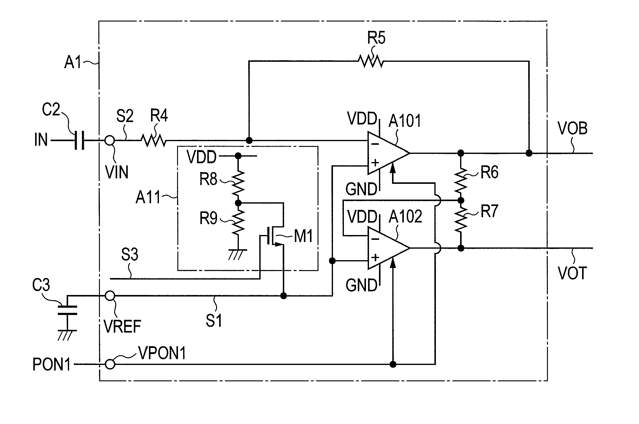
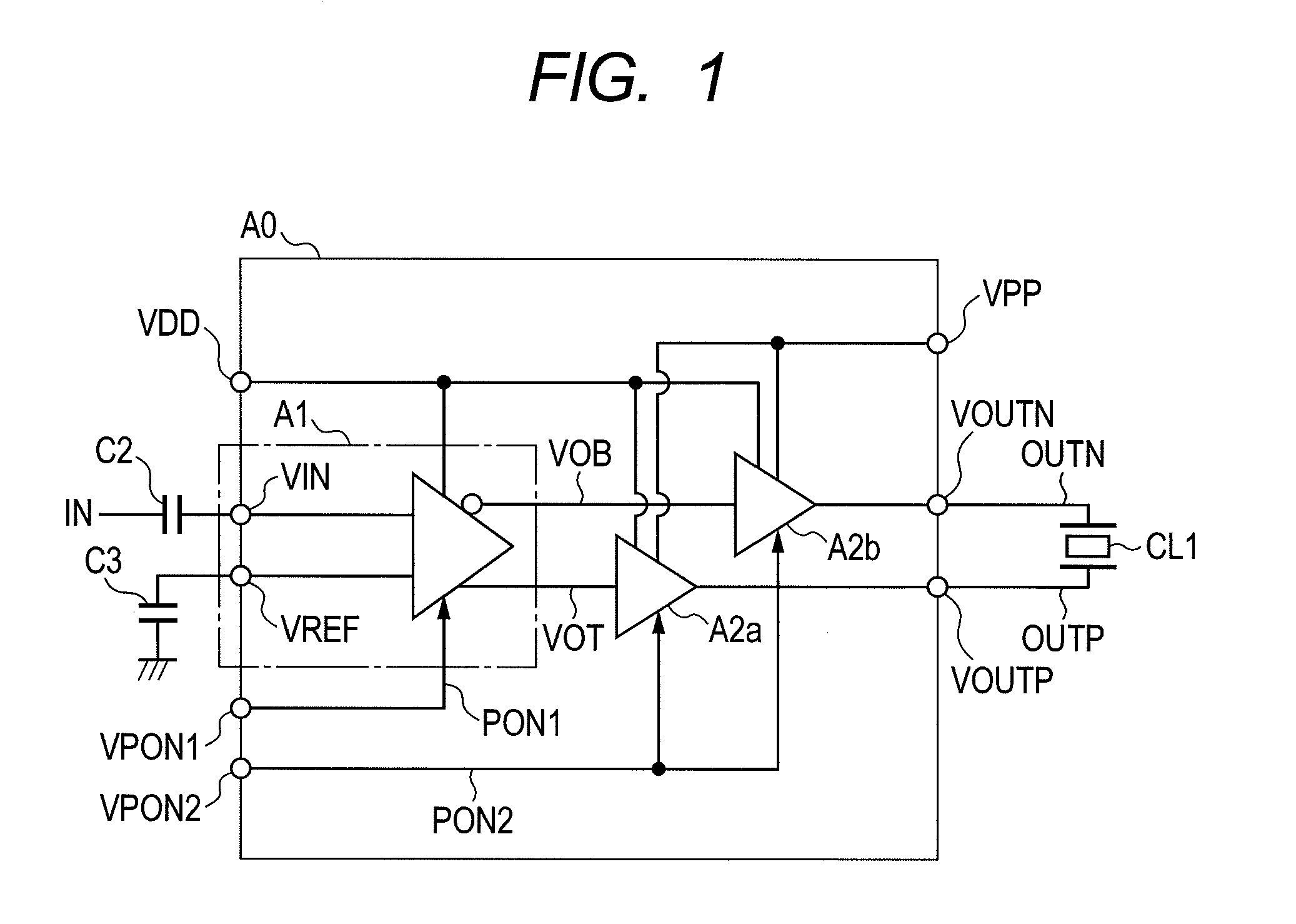
[0025]FIG. 1 is a circuit diagram showing a configuration example of an amplifier circuit according to the first embodiment. As shown in FIG. 1, an amplifier circuit A0 according to the embodiment includes a single-ended-to-differential translate circuit A1, amplifiers A2a and A2b, a capacitor C2, and a stabilizing capacitor C3. The single-ended-to-differential translate circuit A1 converts single input into differential output. The amplifiers A2a and A2b amplify differential outputs VOT and VOB from the single-ended-to-differential translate circuit A1 into high voltages. The capacitor C2 forms a high pass filter. The stabilizing capacitor C3 is connected to a reference voltage terminal VREF. A piezoelectric actuator CL1 is connected to output terminals VOUTP and VOUTN of the amplifiers A2a and A2b and is supplied with output signals OUTP and OUTN from the amplifiers A2a ...

second embodiment

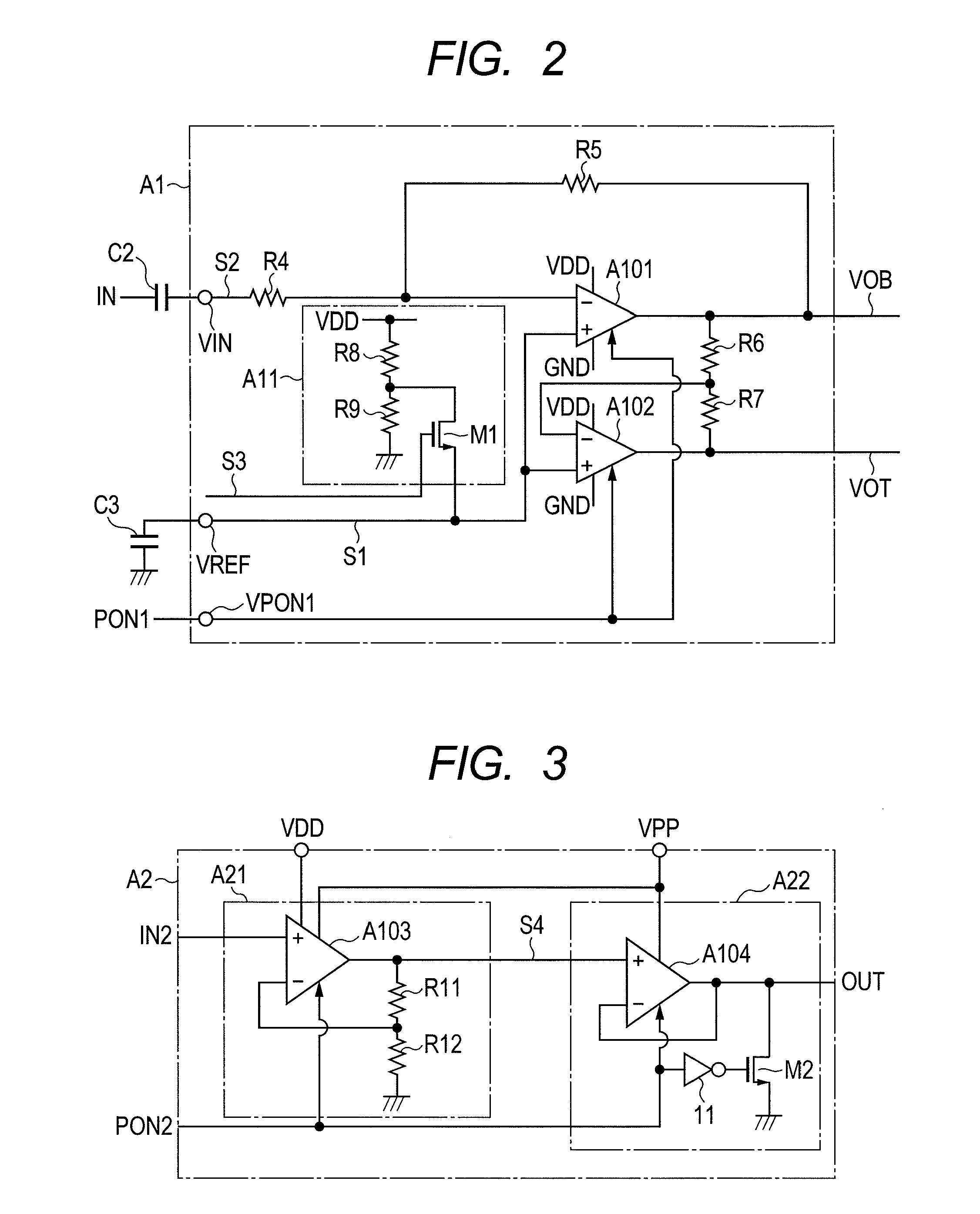
[0055]FIG. 5 is a circuit diagram showing a configuration of an amplifier circuit A10 according to the second embodiment with modifications to the power-on signal control method according to the first embodiment of the invention.

[0056]The second embodiment features a control circuit CTRL. The control circuit CTRL allows a logic circuit using a delay device to generate the signal PON1 supplied to the single-ended-to-differential translate circuit and the signal PON2 supplied to the amplifier circuit from a control signal generation signal PON at a given timing.

[0057]The control circuit CTRL is also capable of adjusting rise / fall timings of the signals PON1 and PON2. For example, the control circuit CTRL is mounted with a register circuit that can provide variable timings corresponding to the times t1, t3, t7, and t9 (see FIG. 4) for turning on or off the control signals PON1 and PON2 output from the control circuit CTRL in accordance with the startup time to be determined later based...


PUM


Abstract

An amplifier circuit is configured to be preceded by a single-ended-to-differential translate circuit using a BTL configuration operating at a low voltage and succeeded by amplifiers to amplify output signals VOT and VOB from the single-ended-to-differential translate circuit. The amplifier circuit activates a mute function of the subsequent amplifiers during state transition when the single-ended-to-differential translate circuit turns on. Consequently, the amplifier circuit fixes output signals OUTP and OUTN to 0 V and masks an output noise. The amplifier circuit inactivates the mute function after signals VOT and VOB become stable. Thereby, the amplifier circuit is capable of easily preventing a pop noise using a BTL configuration requested for high voltage output to drive a piezoelectric actuator.

Description

CLAIM OF PRIORITY[0001]The present application claims priority from Japanese patent application JP 2010-160203 filed on Jul. 15, 2010, the content of which is hereby incorporated by reference into this application.FIELD OF THE INVENTION[0002]The present invention relates to a single-ended-to-differential translate circuit using a bridge-tied load (BTL) configuration. More particularly, the invention relates to a technology capable of preventing a pop noise during power-on / off sequence.BACKGROUND OF THE INVENTION[0003]In many cases, an audio amplifier circuit uses the BTL configuration that applies audio signals of opposite phases to both terminals of a speaker and approximately doubles the amplitude. The reason is that there is an increasing demand to reduce a power supply voltage and generate high output at a low voltage.[0004]In the related art, an audio system is liable to generate a pop noise that generates unpleasant sound from a speaker or a headphone during power-on / off seque...

Claims


Application Information

Patent Timeline
Patent Type & Authority Applications(United States)
IPC IPC(8): H03F3/45
CPCH03F1/305H03G3/348H03F2200/411H03F3/181
Inventor SAHARA, RYUSUKEUENO, SATOSHIKAWATA, TAKAHIRO
Owner HITACHI LTD
Why Eureka
Try Eureka