Memory Compression Technique with Low Latency per Pixel

a memory compression and pixel technology, applied in the field of memory compression for images, can solve the problems of increasing the footprint of images for display, the memory footprint of visual images captured and/or displayed by electronic devices, and the memory footprint of images is often significant, so as to achieve low latency and low latency. the effect of small hardwar

Active Publication Date: 2012-01-19
APPLE INC
View PDF6 Cites 22 Cited by
  • Summary
  • Abstract
  • Description
  • Claims
  • Application Information

AI Technical Summary

Benefits of technology

[0008]In an embodiment, a compression unit is provided which may perform compression of images with low latency and relatively little hardware. Similarly, a decompression unit may be provided which may decompress the images with low latency and little hardware. Such compression / decompression hardware may permit the real time use of compression on images in a system, which may reduce the memory footprint of the images. Bandwidth pressure on the interconnect between the memory and various devices that manipulate images may be lessened, as may competition for memory space between the image data and other data stored in the memory. In one implementation, the compression / decompression hardware may be configured to compress a tile of about 1000 pixels in about 2 clock cycles per pixel, on average, using hardware that is on the order of 10 times smaller (e.g. in terms of transistors) than hardware for handling JPEG or H.254 frames. Other implementations may achieve different results in terms of average clock cycles per pixel and hardware size, and may operate on different sized tiles.
[0009]In an embodiment, color space conversions may be used to reduce the number of color components that may be filtered by filtering hardware and / or software. For example, a red-green-blue (RGB) representation of each pixel may be converted to a YUV representation of the pixel. Most of the image information may lie in the Y component, which may be filtered. The filtered Y component and the unfiltered U and V components may then be converted back to the RGB representation, which may closely approximate the result of filtering each of the R, G, and B components. In another embodiment, a Bayer sensor output may be converted to a YUVW format (and the Y component may be filtered).

Problems solved by technology

Visual images captured and / or displayed by an electronic device are often characterized by a significant memory footprint (i.e. the amount of memory consumed to store data representing the image).
As the resolution of the images increases, the memory footprint of the image increases.
Additionally, such devices are being equipped with higher resolution screens, and thus the footprint of images for display also increases.
Such devices may also be designed to output high resolution images / video to an external device, and the footprint of the high resolution images is large.
While the size of memory in such devices is also increasing over time, the size of the memory is not increasing at the same rate as the image size.
Each application consumes memory for the code being executed and the data being operated upon, which places further pressure on the memory capacity.
However, during image capture and display, the time and hardware required to compress and decompress images is often prohibitive.

Method used


Image

  • Memory Compression Technique with Low Latency per Pixel
  • Memory Compression Technique with Low Latency per Pixel
  • Memory Compression Technique with Low Latency per Pixel

Examples


Embodiment Construction

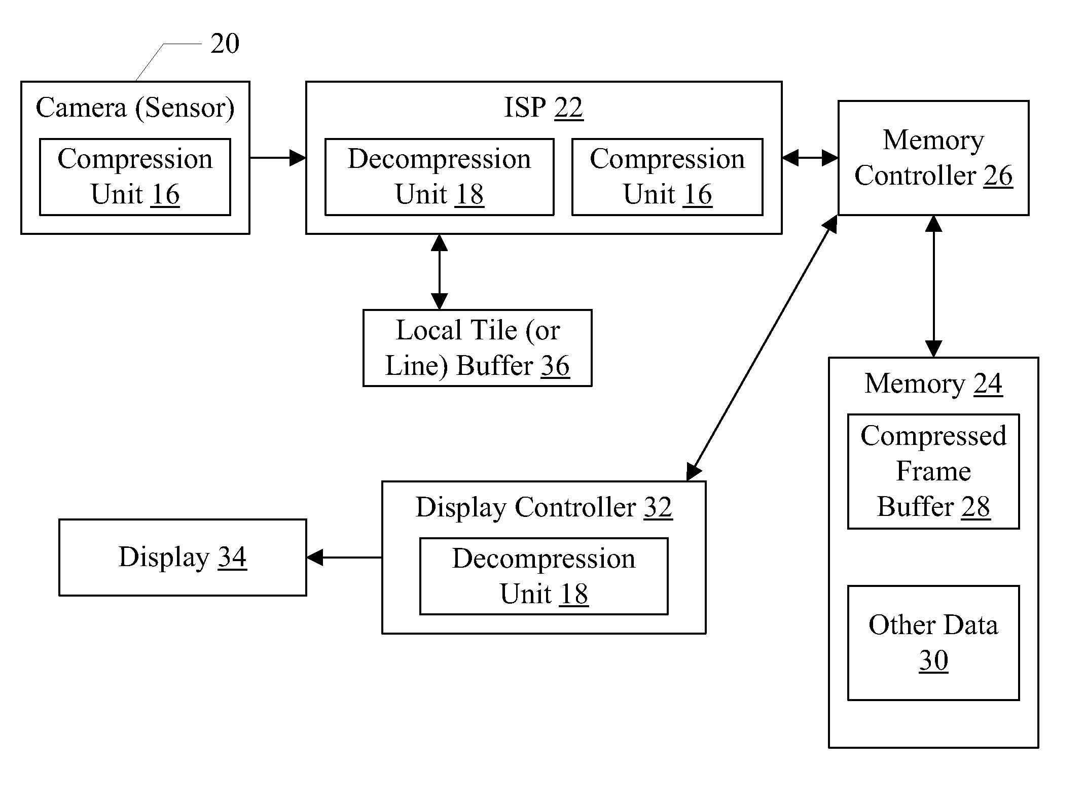
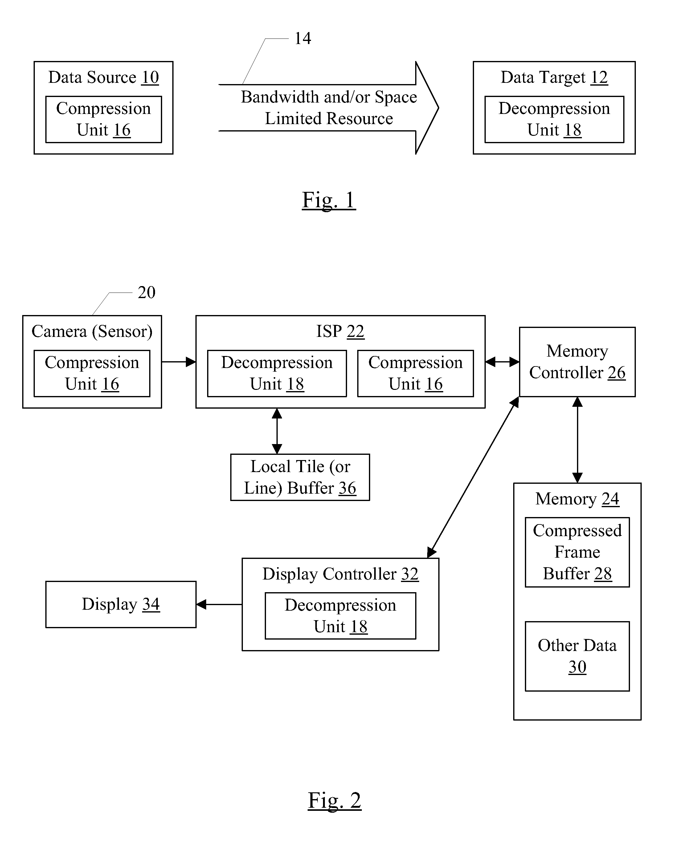
[0029]Turning now to FIG. 1, a block diagram is shown of a generic data source 10 and a generic data target 12 coupled via a channel 14 that includes at least one bandwidth-limited and / or space-limited resource. The data source 10 includes a compression unit 16, and the data target 12 includes a decompression unit 18.

[0030]Generally, the data source 10 may be configured to transfer data over the channel 14 to the data target 12. The data source 10 may generate the data (e.g. the data source 10 may be a sensor, such as a camera for graphical images), or may receive the data from other circuitry and may optionally process the data to transform the data in some defined fashion. The data source 10 may then compress the data using the compression unit 16. Generally, the compression may itself be a transformation of the data, reducing the size of the data in the transformation.

[0031]Compression may be lossless or lossy. With lossless compression, the original data may be recovered in its ...


PUM


Abstract

In an embodiment, a compression unit is provided which may perform compression of images with low latency and relatively little hardware. Similarly, a decompression unit may be provided which may decompress the images with low latency and hardware. In an embodiment, the transmission of compressed coefficients may be performed using less than two passes through the list of coefficients. During the first pass, the most significant coefficients may be transmitted and other significance groups may be identified as linked lists. The linked lists may then be traverse to send the other significance groups. In an embodiment, a color space conversion may be made to permit filtering of fewer color components than might be possible in the source color space.

Description

[0001]This application claim benefit of priority under 35 U.S.C. §119(e) of U.S. Provisional Patent Application Ser. No. 61 / 365,256, filed on Jul. 16, 2010, incorporated herein by reference in its entirety. To the extent that anything in the provisional application conflicts with material expressly set forth herein, the material herein controls.BACKGROUND[0002]1. Field of the Invention[0003]This invention is related to the field of memory compression for images.[0004]2. Description of the Related Art[0005]Visual images captured and / or displayed by an electronic device are often characterized by a significant memory footprint (i.e. the amount of memory consumed to store data representing the image). As the resolution of the images increases, the memory footprint of the image increases. Various electronic devices are expected to be capable of processing such images. For example, mobile electronic devices such as mobile telephones and personal digital assistants are often equipped with...

Claims


Application Information

Patent Timeline
Patent Type & Authority Applications(United States)
IPC IPC(8): G06K9/36H04N5/228G06F12/00
CPCG06F2212/401H04N9/67G06T9/007H04N19/146G06K9/36
Inventor FREDERIKSEN, JEFFREY E.FRANK, MICHAEL
Owner APPLE INC
Why Eureka
Try Eureka