Superconducting coil, superconducting magnet, and method of operating superconducting magnet

a superconducting magnet and superconducting coil technology, applied in the direction of superconducting magnets/coils, magnets, magnetic bodies, etc., can solve the problems of easy quench, the circuit cannot be forcibly opened, and the difficulty of superconducting coil quench protection

Active Publication Date: 2012-01-19
HITACHI LTD
View PDF3 Cites 21 Cited by
  • Summary
  • Abstract
  • Description
  • Claims
  • Application Information

AI Technical Summary

Benefits of technology

[0032]According to the present invention, in the superconducting magnet being operated in the persistent mode, when the quench occurs, a superconducting coil, a s

Problems solved by technology

However, in a persistent mode continuing the current flow through a closed circuit including the superconducting coil and a persistent current switch, the circuit cannot be forcibly opened.
On the other hand, the quench protection becomes more difficult in superconducting magnets (superconducting coils) using a high temperature superconducting wire including, for example, a magnesium diboride (MgB2) than the case using the low temperature superconducting wire.
In addition, because the higher the temperature of the high temperature superconductor, the larger specific heat the high temperature superconductor ha

Method used


Image

  • Superconducting coil, superconducting magnet, and method of operating superconducting magnet
  • Superconducting coil, superconducting magnet, and method of operating superconducting magnet
  • Superconducting coil, superconducting magnet, and method of operating superconducting magnet

Examples


first embodiment

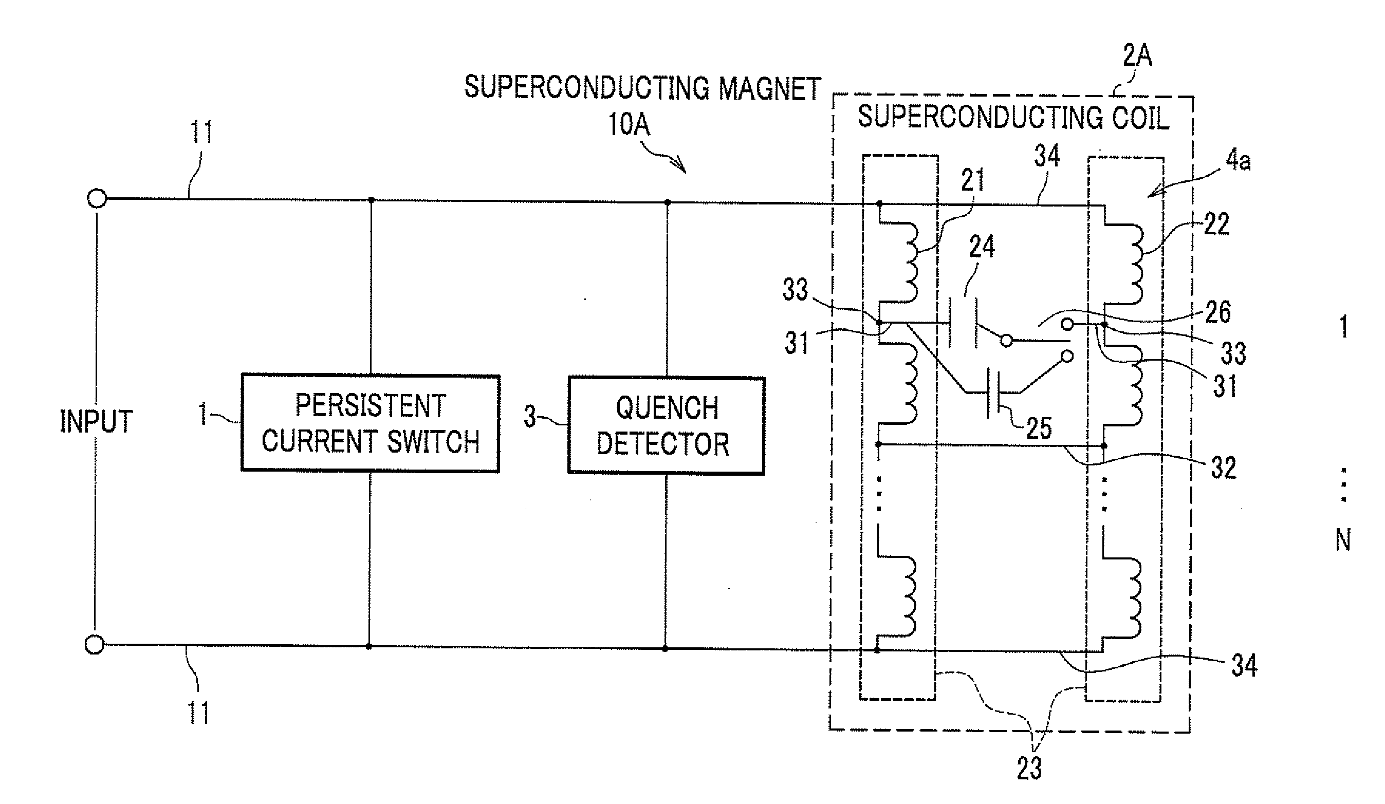
[0059]The superconducting magnet 10A (10) and the superconducting coil 2A (2) according to the first embodiment will be described with reference to FIG. 2. In the first embodiment, a current is supplied to the superconducting wire 21 by discharging a capacitor 24.

[0060]FIG. 2 is an equivalent circuit diagram of the superconducting magnet according to the first embodiment.

[0061]Two superconducting wires 21 and 22 are bundled and wound together as a parallel conductor (electrically-parallel-connection conductor) 23 on a bobbin in a coil state to form a superconducting coil 2A and electrically connected to an input of the superconducting magnet 10A in parallel. In other words, superconducting wires 21 and 22 has at least two connections 34 therebetween for parallel connection. Both ends of the superconducting coil 2 A are respectively connected to the persistent current switch 1 and the quench detector 3 in parallel.

[0062]The superconducting coil 2A further includes a protection circu...

second embodiment

[0092]A superconducting magnet 10B (10) and a superconducting coil 2B (2) according to a second embodiment will be described. In the second embodiment, an LC resonating circuit including an inductance L and a capacitance C is used to supply the current to the superconducting wires 21 and 22 in response to detection of the quench.

[0093]FIG. 6 is an equivalent circuit of the superconducting magnet according to the second embodiment.

[0094]Two superconducting wires 21 and 22 are bundled as a parallel conductor 23 and wound together around a bobbin in a coil to form the superconducting coil 2B.

[0095]Both ends of the superconducting coil 2B are connected to the persistent current switch 1 and the quench detector 3.

[0096]The superconducting coil 2B has a protection circuit 4b including capacitors 24 and an AC voltage supply 27.

[0097]At least one capacitor 24 is connected to the parallel conductor 23 (the intermediate points 33 of the superconducting wires 21, 21 ) of the superconducting ...

third embodiment

[0112]A superconducting magnet 10C (10) and a superconducting coil 2C (2) according to a third embodiment will be described.

[0113]FIG. 9 is an equivalent circuit of the superconducting magnet according to the third embodiment.

[0114]Two superconducting wires 21 and 22 are bundled as a parallel conductor 23 and wound together around the bobbin in the coil to form the superconducting coil 2C.

[0115]Both ends of the superconducting coil 2C are connected to the persistent current switch 1 and the quench detector 3 and have connections 34.

[0116]The superconducting coil 2C has a protection circuit 4c including a current source 28. The current source 28 supplies a current on the basis of the detection signal of the quench detector 3. The current source 28 has a large capacity to rapidly supply a large intensity of the current.

[0117]According to the superconducting magnet 10C (superconducting coil 2B) according to the third embodiment, it is possible to rapidly supply the current of which in...


PUM


Abstract

In a superconducting coil, a parallel conductor includes a plurality of superconducting wires bundled and wound in a coil. The superconducting wires have at least two connections therebetween. A current source connected to the superconducting wires to form a loop via the superconducting wires and the connection to supply a current in the loop when a quench is detected. A superconducting magnet includes the superconducting coil, a persistent current switch connected to the superconducting coil, and a quench detector configured to detect quench occurring in the superconducting coil.

Description

CROSS REFERENCE TO RELATED APPLICATION[0001]This application claims the foreign priority benefit under Title 35, United States Code, §119(a)-(d) of Japanese Patent Application No. 2010-159382, filed on Jul. 14, 2010 in the Japan Patent Office, the disclosure of which is herein incorporated by reference in its entirety.BACKGROUND OF THE INVENTION[0002]1. Field of the Invention[0003]The present invention relates to a superconducting coil, a superconducting magnet, and a method of operating the superconducting magnet and particularly to quench protection for a superconducting coil in a superconducting magnet operated in a persistent mode.[0004]2. Description of the Related Art[0005]Because a superconducting magnet used in an MRI (Magnetic Resonance Imaging) apparatus, an NMR (Nuclear Magnetic Resonance) or the like generally require a high intensity magnetic field, a magnetic energy (LI2 / 2, where L is an inductance and I is driving current) stored in the coil of a superconducting magne...

Claims


Application Information

Patent Timeline
IPC IPC(8): H01F6/06
CPCH01F6/02
Inventor ICHIKI, YOTAWAKUDA, TSUYOSHIPARK, MINSEOK
Owner HITACHI LTD
Why Eureka
Try Eureka