Device and method for producing control data for the surgical correction of defective eye vision

a technology for producing control data and surgical correction, applied in the field of devices and methods for producing control data for surgical correction of defective eye vision, can solve the problems of limited correction possibilities, degree of limitation of possible correction, and the empirical values developed for grinding the cornea by means of laser radiation cannot be used for such methods, and achieves the effect of facilitating the number of rotations

Active Publication Date: 2012-01-19
CARL ZEISS MEDITEC AG
View PDF1 Cites 23 Cited by
  • Summary
  • Abstract
  • Description
  • Claims
  • Application Information

AI Technical Summary

Benefits of technology

[0062]In combination with the production of a cut surface in which the focus of the treatment laser radiation is shifted along a path, there are different possibilities for setting the curves of the path, such that adapting the non-rotation-symmetrical edge to the circular contour, thus the transition area, can be defined particularly easily. In a first variant it is provided that the laser treatment device is adapted to focus treatment laser radiation into the cornea of the eye along a main direction of incidence and to shift the position of the laser focus within the cornea, that the rotation-symmetrical edge is fixed, and that the control data are generated such that they define a path along which the laser focus is to be shifted, wherein the path lies in the predetermined correction surface and runs spirally from inside the predetermined correction surface to its edge, wherein the control data continue the spiral in the transition area such that one each revolution the distance between the edge of the predetermined correction surface and the rotation-symmetrical edge is reduced according to a predetermined function, preferably linearly.
[0063]The spiral thus reduces in each revolution the distance between the edge of the predetermined correction surface and the rotation-symmetrical (circular) edge according to a predetermined function. In areas in which the distance between the non-rotation-symmetrical edge of the correction surface and the circular edge is a short distance, the paths thus become narrower, in areas in which there is a comparatively greater distance the paths are spaced further apart. The minimum or maximum distance between successive revolutions of the spiral can be set particularly easily through the number of rotations and the choice of the function.

Problems solved by technology

Empirical values which have been developed for grinding the cornea by means of ablation laser radiation cannot be used for such methods.
However, this simplification also means a degree of limitation of the possible correction results, because inevitably only corrections which would also be possible with normal spectacles can be achieved.
The approach known from DE 102006053120 A1 can thus consequently use only comparatively simple spectacle defective-vision correction data as an input variable for control data, with the consequence of correspondingly limited possibilities of correction.
As this shift of the focus is generally much slower than the deflection across the main direction of incidence of the treatment laser radiation, the result is a rapid production of the cut surface.

Method used


Image

  • Device and method for producing control data for the surgical correction of defective eye vision
  • Device and method for producing control data for the surgical correction of defective eye vision
  • Device and method for producing control data for the surgical correction of defective eye vision

Examples


Embodiment Construction

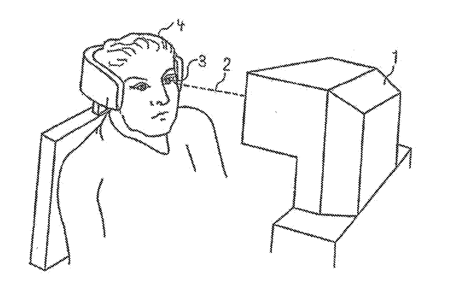
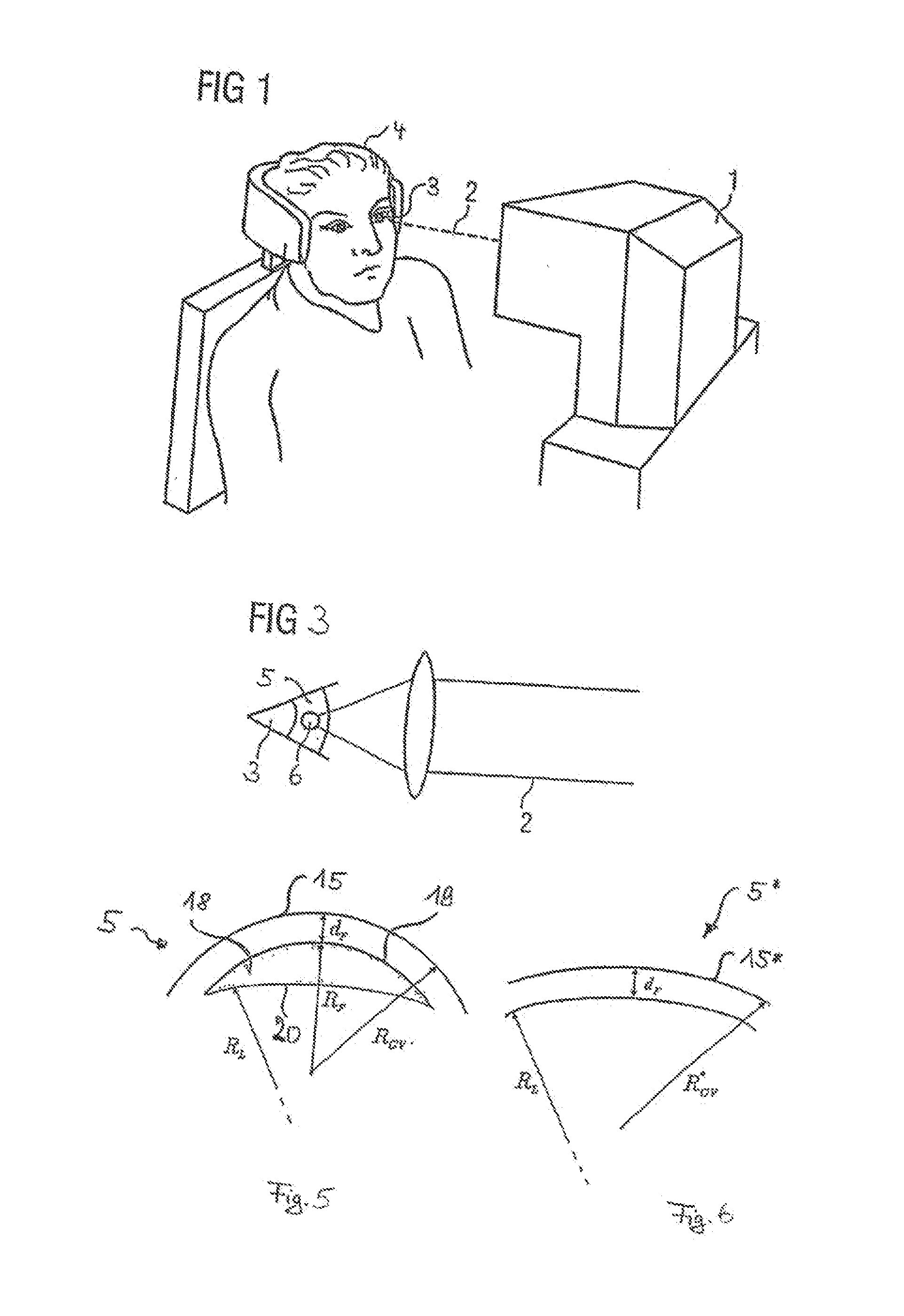
[0087]FIG. 1 shows a treatment apparatus 1 for an eye-surgery procedure which is similar to that described in EP 1159986 A1 or in U.S. Pat. No. 5,549,632. By means of a treatment laser radiation 2 the treatment apparatus 1 effects a correction of defective vision on an eye 3 of a patient 4. Defective vision can include hyperopia, myopia, presbyopia, astigmatism, mixed astigmatism (astigmatism in which there is hyperopia in one direction and myopia in a direction lying at right angles thereto), aspherical errors and higher-order aberrations. In the embodiment described, the treatment laser radiation 2 is applied as a pulsed laser beam focused into the eye 3. The pulse duration in this case is e.g. in the femtosecond range, and the laser radiation 2 acts by means of non-linear optical effects in the cornea. The laser beam has short laser pulses of e.g. 50 to 800 fs (preferably 100-400 fs) with a pulse repetition frequency of between 10 and 500 kHz. In the embodiment described, the mod...


PUM


Abstract

A device for producing control data for a laser device for the surgical correction of defective vision. The device produces the control data such that the laser emits the laser radiation such that a volume in the cornea is isolated. The device calculates a radius of curvature RCV* to determine the control data, the cornea reduced by the volume having the radius of curvature RCV* and the radius of curvature being site-specific and satisfying the following equation: RCV*(r,φ)=1/((1/RCV(r,φ))+BCOR(r,φ)/(nc−1))+F, wherein RCV(r,φ) is the local radius of curvature of the cornea before the volume is removed, nc is the refractive index of the material of the cornea, F is a coefficient, and BCOR(r,φ) is the local change in refractive force required for the desired correction of defective vision in a plane lying in the vertex of the cornea, and at least two radii r1 and r2 satisfy the equation BCOR(r=r1,φ)≠BCOR(r=r2,φ).

Description

PRIORITY CLAIM[0001]The present application is a National Phase entry of PCT Application No. PCT / EP2010 / 050700, filed Jan. 21, 2010, which claims priority from German Application Number 102009005482.0, filed Jan. 21, 2009, the disclosures of which are hereby incorporated by reference herein in their entirety.FIELD OF THE INVENTION[0002]In a first variant the invention relates to a device for generating control data for controlling a laser for the surgical correction of the defective vision of an eye of a patient, wherein the control data are adapted to control a laser which cuts cornea tissue by irradiating laser radiation into the cornea of the eye, the device generates the control data such that the laser, during operation according to the control data, emits the laser radiation such that a volume in the cornea is isolated, the removal of which from the cornea effects the desired correction of defective vision and, to determine the control data, the device calculates a radius of c...

Claims


Application Information

Patent Timeline
Patent Type & Authority Applications(United States)
IPC IPC(8): A61F9/01
CPCA61F9/008A61F9/00827A61F9/00829A61F2009/00882A61F9/00838A61F2009/00872A61F2009/0088A61F9/00836
Inventor STOBRAWA, GREGORBISCHOFF, MARK
Owner CARL ZEISS MEDITEC AG
Why Eureka
Try Eureka