Semiconductor fabrication apparatus and temperature adjustment method

a technology of semiconductor wafers and fabrication apparatuses, applied in the direction of instruments, electric discharge tubes, fluid pressure control using electric means, etc., can solve the problems of increased power consumption of pumps to deliver temperature adjustment mediums, poor responsiveness of temperature control, and difficulty in uniform temperature adjustment of semiconductor wafers, etc., to achieve uniform temperature adjustment and high responsiveness of semiconductor wafers

Inactive Publication Date: 2012-01-19
TOKYO ELECTRON LTD
View PDF5 Cites 25 Cited by
  • Summary
  • Abstract
  • Description
  • Claims
  • Application Information

AI Technical Summary

Benefits of technology

[0020]It is possible to achieve uniform temperature adjustment and high responsiveness of the semiconductor wafer as compared to conventional temperature adjustment methods.

Problems solved by technology

However, such forced convection type temperature adjustment has a limited passage heat transfer property, which results in difficulty in uniform semiconductor wafer temperature adjustment and poor responsiveness of temperature control.
However, there is a trade-off between the passage heat transfer property and a pressure loss.
That is, improvement in the passage heat transfer property leads to increase in the pressure loss, which may result in increased power consumption of a pump to deliver the temperature adjustment medium.
On the contrary, decrease in the pressure loss to achieve power saving leads to deterioration of the passage heat transfer property due to increase a temperature difference between an inlet side and an outlet side of the temperature adjustment medium, which results in difficulty in uniform temperature adjustment of the semiconductor wafer.
However, since the semiconductor wafer mounting table is provided with various types of screws, lift pins, electrode parts and so on, there are various restrictions on a space for the passage and it is extremely difficult to achieve an optimization for passage design.

Method used


Image

  • Semiconductor fabrication apparatus and temperature adjustment method
  • Semiconductor fabrication apparatus and temperature adjustment method
  • Semiconductor fabrication apparatus and temperature adjustment method

Examples


embodiment 2

[0079]FIG. 6A is a side sectional view of a wafer mounting table 102 and a water jet 164 according to Embodiment 2 and FIG. 6B is a plan view of the water jet 164 according to Embodiment 2. A semiconductor fabrication apparatus according to Embodiment 2 has the same structure as the semiconductor fabrication apparatus according to Embodiment 1 except a shape of a cavity 121 of the wafer mounting table 102 and a structure of the water jet 164 and therefore a difference therebetween will be mainly described below.

[0080]The cavity 121 formed in the wafer mounting table 102 according to Embodiment 2 includes a bottom inner wall 121a, a circumferential wall 121b and a ceiling inner wall 121c. The bottom inner wall 121a and the ceiling inner wall 121c have an inclination surface inclined with respect to a mounting surface on which the semiconductor wafer W is mounted. More specifically, the ceiling inner wall 121c has its apex at the bottom of the central portion of the wafer mounting tab...

embodiment 3

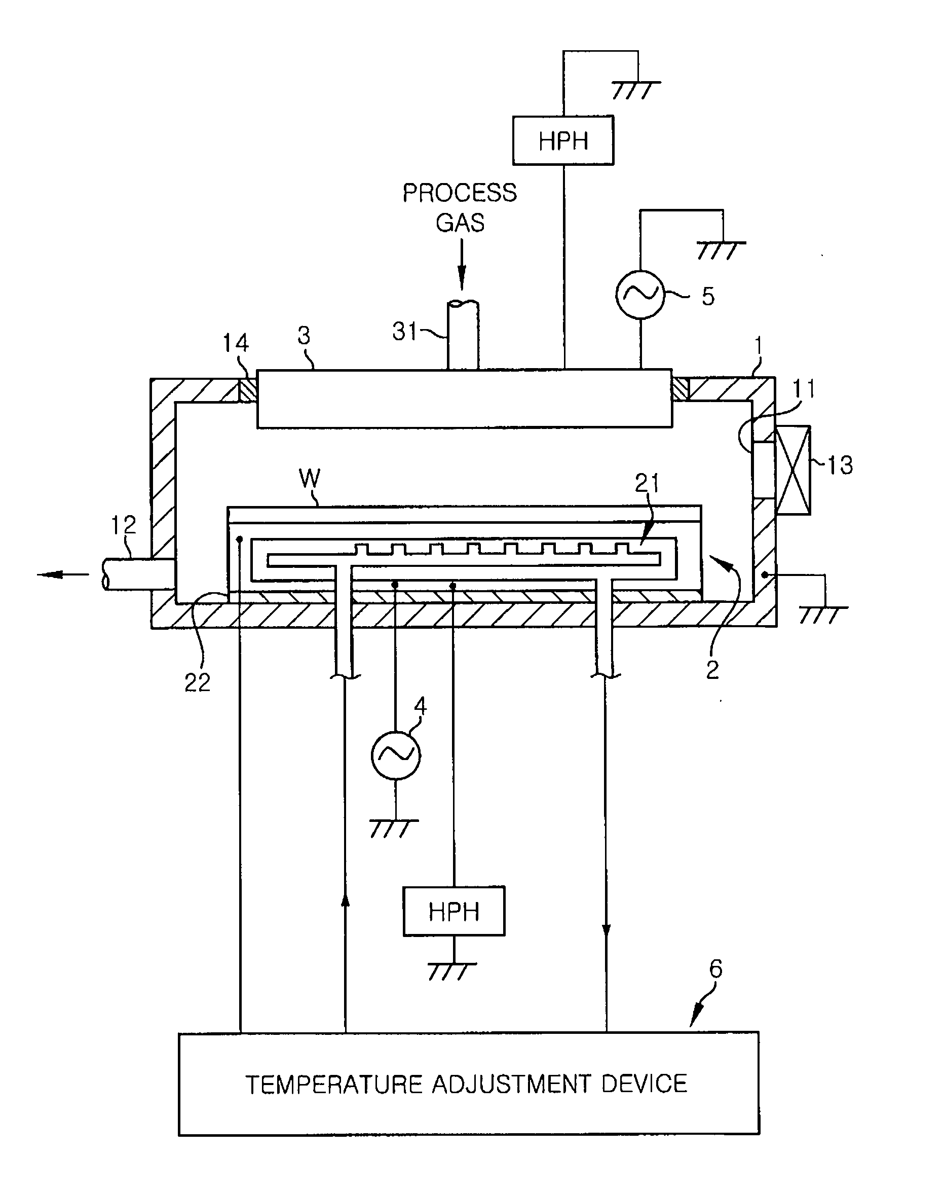
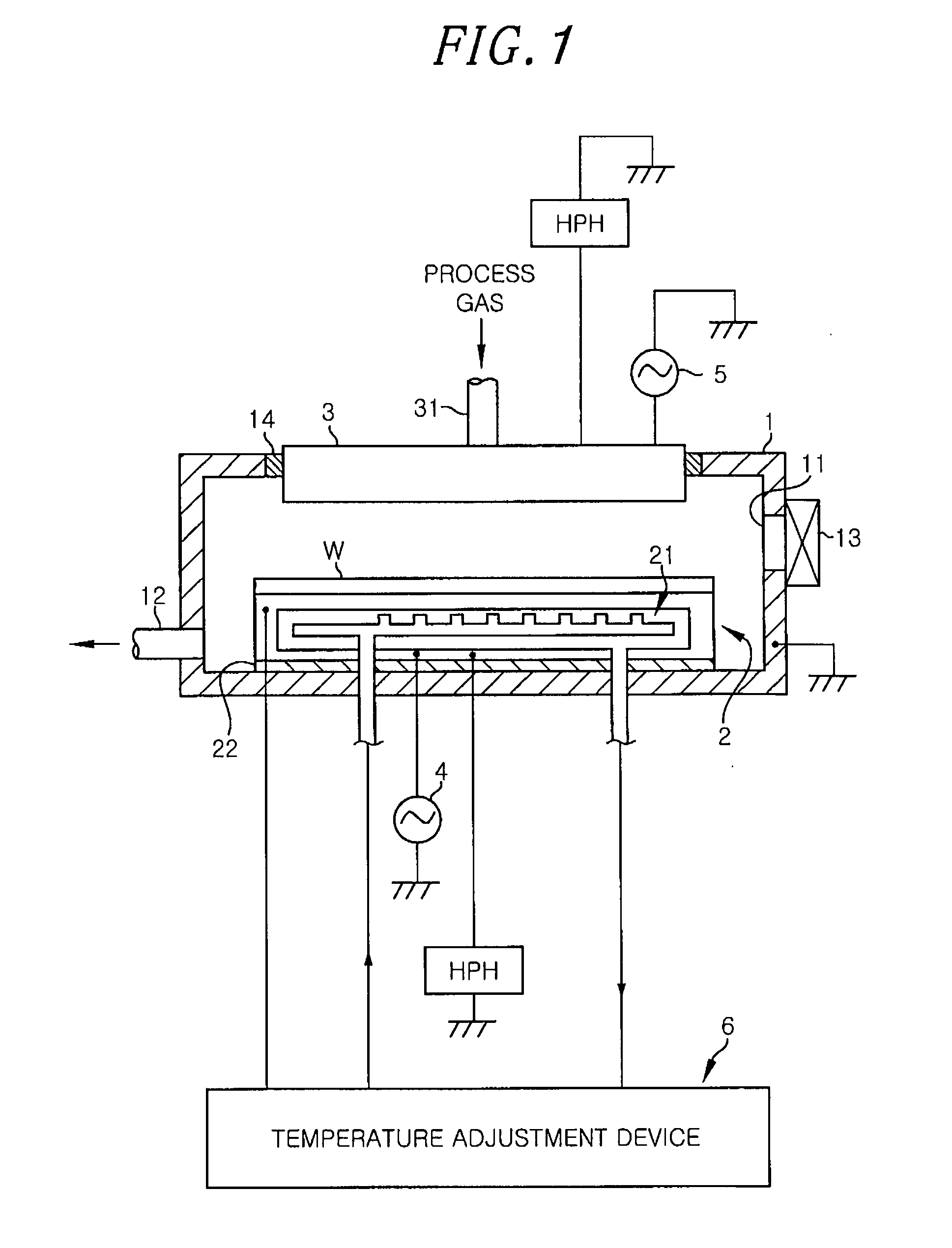
[0089]FIG. 8 is a schematic view showing the wafer mounting table 2 and a temperature adjustment device 306 according to Embodiment 3. A semiconductor fabrication apparatus according to Embodiment 3 involves adjustment of heating temperature of the wafer mounting table 2 by feeding saturated vapor into the cavity of the wafer mounting table 2. The semiconductor fabrication apparatus according to Embodiment 3 has the same structure as Embodiment 1 except a structure of the wafer mounting table 2 and the temperature adjustment device 306 and therefore a difference therebetween will be mainly described below.

[0090]The temperature adjustment device 306 according to Embodiment 3 includes a vapor pressure controller 73 for feeding saturated vapor into the cavity 21 and a temperature reducer 74 instead of the water jet 64, the temperature controller 62 and the flow rate sensor 72 described in Embodiment 1. In addition, a vapor feeding hole (temperature adjustment medium feeding hole) 21e i...

embodiment 4

[0102]FIG. 11 is a schematic view showing a wafer mounting table 2 and a temperature adjustment device 406 according to Embodiment 4. A semiconductor fabrication apparatus according to Embodiment 4 is configured to cool and heat the wafer mounting table 2 by a combination of elements of Embodiments 1 and 3.

[0103]The wafer mounting table 2 according to Embodiment 4 contains the cavity 21 where the water jet 64 is arranged, as in Embodiment 1. In addition, it has the vapor feeding hole 21e formed in an appropriate place of the bottom inner wall 21a, as in Embodiment 3.

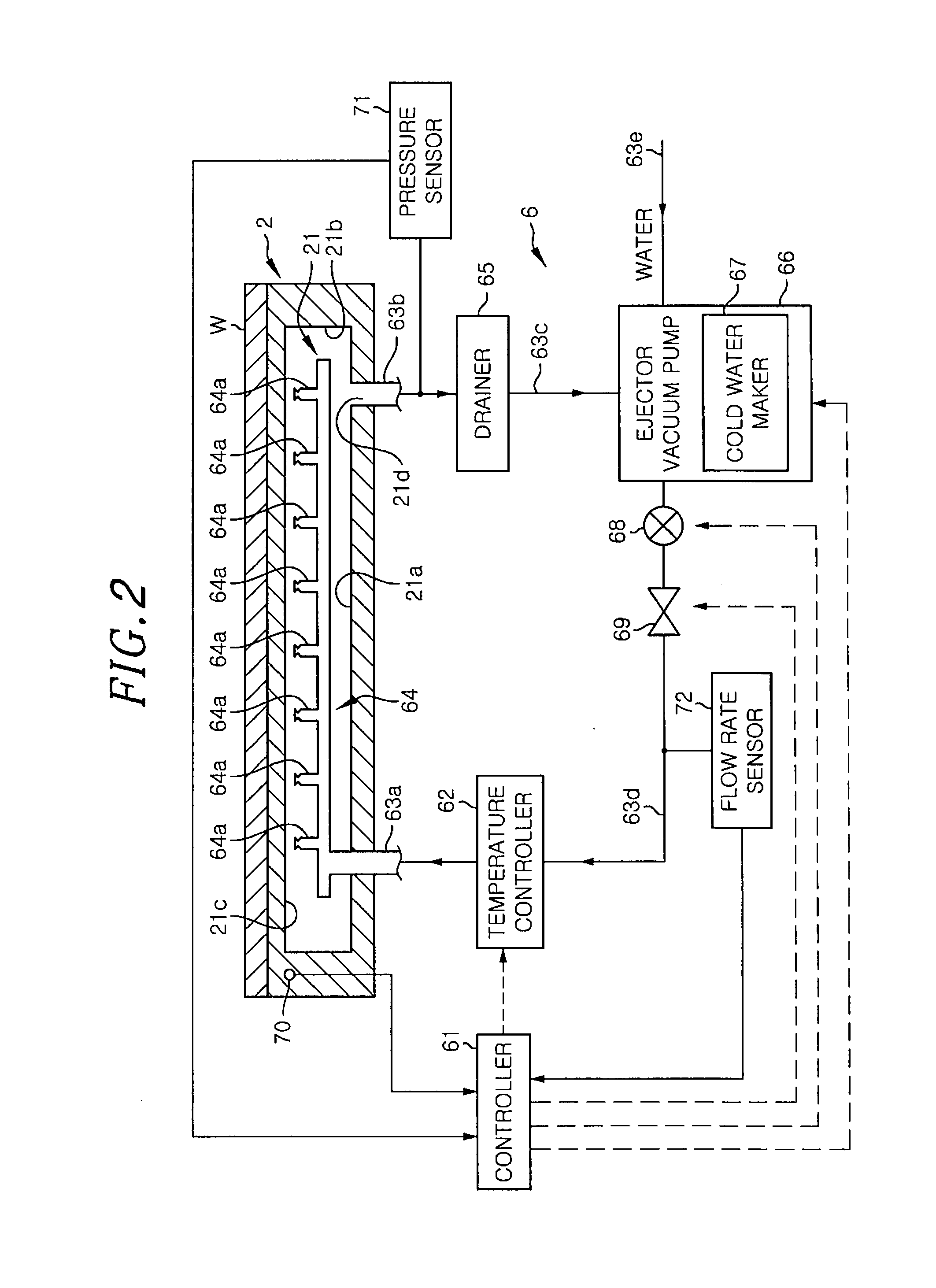
[0104]The temperature adjustment device 406 according to Embodiment 4 includes the controller 61, the temperature controller 62, the water jet 64, the drainer 65, the ejector vacuum pump 66, the cold water maker 67, the water feeding pump 68, the flow rate control valve 69, the temperature sensor 70, the pressure sensor 71 and the flow rate sensor 72, as in Embodiment 1. In addition, the temperature adjustment device 406...


PUM


Abstract

A semiconductor fabrication apparatus includes a semiconductor wafer mounting table having a cavity therein; and a nozzle which jets a liquefied temperature adjustment medium having a temperature equal to or less than a targeted temperature to an inner wall of the cavity in order to adjust a temperature of the semiconductor wafer mounting table to the targeted temperature. The semiconductor fabrication apparatus further includes a pressure detecting unit for detecting an internal pressure of the cavity; and a vacuum pump which discharges gas within the cavity such that a pressure detected by the pressure detecting unit becomes equal to or more than a saturated vapor pressure related to the temperature of the temperature adjustment medium jetted from the nozzle and equal to or less than a saturated vapor pressure related to the targeted temperature.

Description

FIELD OF THE INVENTION[0001]The present invention relates to a semiconductor fabrication apparatus with a temperature adjustment function of a semiconductor wafer mounting table and a method of adjusting temperature of the semiconductor wafer mounting table.BACKGROUND OF THE INVENTION[0002]A semiconductor fabrication apparatus includes a temperature adjustment device to keep a semiconductor wafer at a process temperature. The temperature adjustment device carries out temperature adjustment by circulating a liquid for temperature adjustment (hereinafter referred to a “temperature adjustment medium”) in a passage formed inside the semiconductor wafer mounting table (for example see Patent Documents 1 and 2). Such a temperature adjustment method is called a “forced convection method.”[0003]Patent Document 1: Japanese Patent Application Publication No. 2001-44176[0004]Patent Document 2: Japanese Patent Application Publication No. H7-235588[0005]However, such forced convection type tempe...

Claims


Application Information

Patent Timeline
Patent Type & Authority Applications(United States)
IPC IPC(8): G06F17/00G05D16/20G05D23/19
CPCH01J37/32449H01J37/32522H01J37/32623H01L21/67253H01L21/67109H01L21/67248H01J2237/2001
Inventor MATSUZAKI, KAZUYOSHINAGASEKI, SUMIE
Owner TOKYO ELECTRON LTD
Why Eureka
Try Eureka