
High power-density, high efficiency, non-permanent magnet electric machine

Active Publication Date: 2012-01-26
GENERAL ELECTRIC CO
View PDF23 Cites 5 Cited by
  • Summary
  • Abstract
  • Description
  • Claims
  • Application Information

AI Technical Summary

Benefits of technology

[0010]It would therefore be desirable to provide a non-permanent magnet electri

Problems solved by technology

However, the drive motor technology available for hybrid-electric and electric vehicles has generally been cost-prohibitive, thereby reducing one (or both) of consumer affordability or manufacturer profitability.
However, in order to obtain such high power density, IPM machines must use expensive sintered high energy-product magnets.
Furthermore, IPM machines run at high speed (e.g., 14,000 rpm) to obtain optimum power density, and this high speed operation results in a high back electromagnetic field (EMF).
Such high back EMF requires the use of high voltage inverter devices, which results in further increases in overall system costs.
IPM machines also involve intricate rotor and stator designs that are sensitive to high speed operation, thereby increasing the complexity and cost of their manufacture.
These windings are expensive to produce using conventional automatic winding machines.
While special automatic winding machine stations may be developed to produce such windings, such tooling customization is also quite costly.
Distributed winding coils also extend beyond the stator core on which they are wound, which may be disadvantageous for use in tight packaging situations such as those present in electric and / or hybrid-electric vehicles.
These thin bridges result in a weakened mechanical connection, which may be problematic due to high centrifugal forces when the rotor is operated at high speeds.
The need for a small air gap means that both the stator and rotor must be manufactured with tighter tolerances, thereby adding to the complexity and cost of their construction.
Another drawback to the use of IPM machines is the need for sintered magnets to be used in the rotor if high power-density is to be achieved.
This process of rotor construction is not easily automated, again adding to the overall expense of manufacturing IPM machines.
For at least the reasons set forth above, the high costs of manufacturing and maintaining IPM machines have limited both the commercialization of hybrid-electric and electric vehicles and the adoption of electric drive motor technology in general.

Method used


Image

  • High power-density, high efficiency, non-permanent magnet electric machine
  • High power-density, high efficiency, non-permanent magnet electric machine
  • High power-density, high efficiency, non-permanent magnet electric machine

Examples


Embodiment Construction

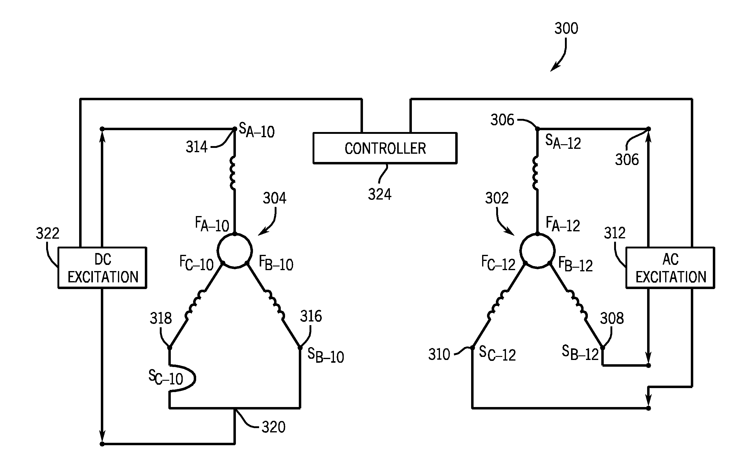
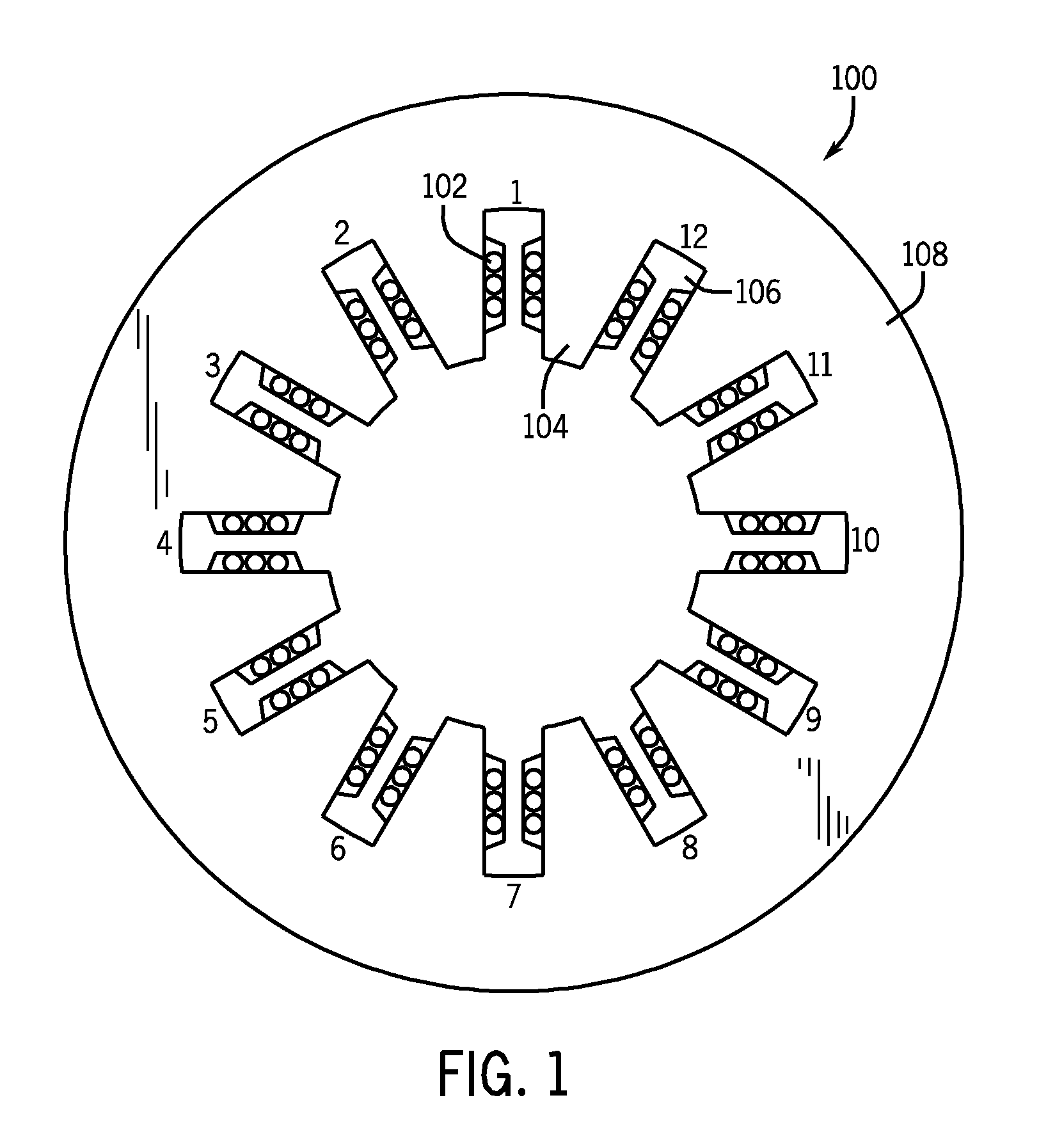
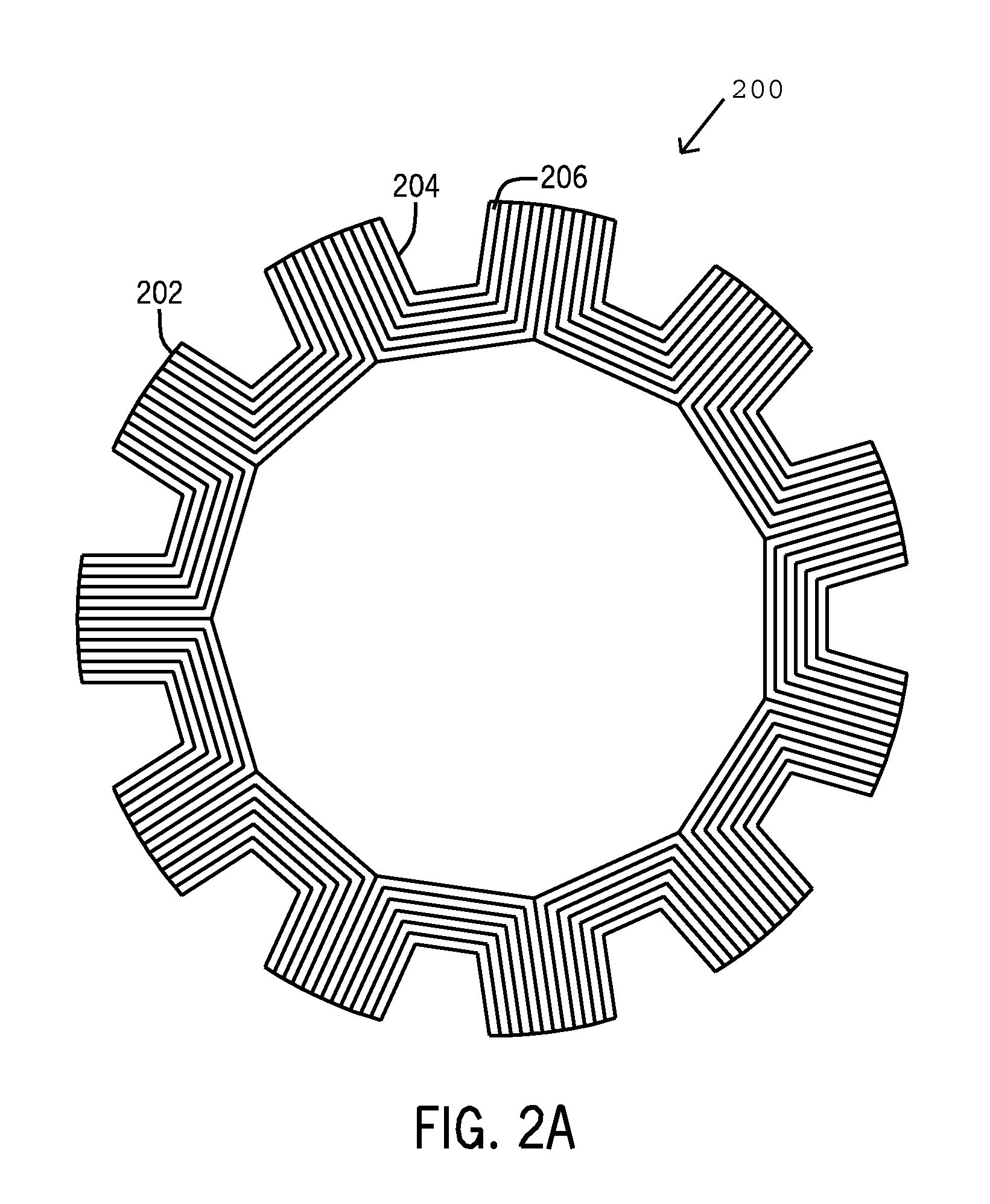
[0022]A system is shown to provide a high power-density, high efficiency, and relatively low cost electric machine for use in a variety of applications, including electric and hybrid-electric vehicle traction applications.

[0023]While many types of electric machines have been utilized for both drive motor and generation applications, the options for high speed and high power-density applications (such as electric and hybrid-electric vehicle traction applications) have typically been limited by cost and / or performance restraints. As previously noted, many electric and hybrid-electric vehicles utilize internal permanent magnet (IPM) electric machines, which are both costly to produce and risk mechanical failure at high speeds. Embodiments of the invention, however, incorporate a synchronous reluctance electric machine equipped with fractional-slot concentrated windings for high power-density operation without the cost or performance restraints previously found in the industry.

[0024]FIG...


PUM

PropertyMeasurementUnit
Poweraaaaaaaaaa
Electric potential / voltageaaaaaaaaaa
Frequencyaaaaaaaaaa

Abstract

A system and method of manufacturing an electric machine comprising a rotor and a stator, wherein the stator comprises a fractional-slot concentrated winding having two sets of terminals, wherein a first set of terminals configures the fractional-slot concentrated winding to have a first pole-number (P1), and wherein a second set of terminals configures the fractional-slot concentrated winding to have a second pole number (P2) different from the first pole-number (P1).

Description

BACKGROUND OF THE INVENTION[0001]Embodiments of the invention relate generally to electric machines having high power-density and, more particularly, to non-permanent magnet electric machines having high efficiency and low cost.[0002]The need for high power density and high efficiency electric machines (i.e., electric motors and generators) has long been prevalent for a variety of applications, particularly for hybrid and / or electric vehicle fraction applications. Due to energy supply and environmental reasons, there has been increased motivation to produce hybrid-electric and / or electric vehicles that are both highly efficient and reliable, yet reasonably priced for the average consumer. However, the drive motor technology available for hybrid-electric and electric vehicles has generally been cost-prohibitive, thereby reducing one (or both) of consumer affordability or manufacturer profitability.[0003]Most commercially available hybrid-electric and electric vehicles rely on interna...

Claims


Application Information

Patent Timeline
IPC IPC(8): H02K37/02
CPCH02K19/12H02K19/20H02K2213/03Y10T29/49117H02K19/103H02K3/28H02K19/26H02K1/16H02K11/00
Inventor ELANTABLY, AHMED MOSTAFAEL-REFAIE, AYMAN MOHAMED FAWZIKING, ROBERT DEAN
Owner GENERAL ELECTRIC CO
Learn More