
Apparatus for a pipe string of a geological drill hole, pipe string, method for operating a geological drilling gear and method for producing a pipe string for a geological drill hole

Inactive Publication Date: 2012-02-02
GEOFORSCHUNGSZENT POTSDAM A CORP OF GERMANY
View PDF5 Cites 5 Cited by
  • Summary
  • Abstract
  • Description
  • Claims
  • Application Information

AI Technical Summary

Benefits of technology

[0009]The object of the invention is to specify improved technologies for constructing or forming a geological drill hole. More efficient handling of drilling flushing liquid should in particular be made possible, and damage to drilled geological formations should be minimised or completely avoided.
[0014]Another aspect of the invention relates to a method for installing a pipe string for a geological drill hole with the above-mentioned apparatus, in which a pipe string element is cemented, and during the cementing a pumping pressure is reduced by a fluid being supplied via a fluid supply line extending along and outside the pipe string element and added to a space to be cemented via a fluid injection device provided on the pipe string element. The reduction of the pumping pressure lowers the risk of geological formations breaking up.
[0015]With the aid of the invention new technologies for constructing a geological drill hole with a pipe string are created, which allow more efficient handling of the drilling machine used in comparison with the prior art. The introduction of the fluid supplied via the fluid supply line in the inner space of the pipe string element allows the density conditions in the operating liquid conveyed upwards, which is usually what is known as a flushing or drilling flushing liquid to be influenced in a targeted manner. For example, the density of the operating liquid can be reduced by introducing a gas. The pressure conditions in the drill hole are thereby adjusted during hole. Also in connection with the method for installing a pipe string, the supply and introduction of the fluid make it possible to regulate the pressure, namely to reduce the pumping pressure during cementing,
[0016]The provision of the fluid supply line outside the pipe string element makes possible an independent design and configuration of the inner space of the pipe string element on the one hand and of the fluid supply line on the other. The pipe string element can be optimised for the intended purpose, in particular the return of the operating liquid and the injection of the fluid into the operating liquid transported back. Independently of this, the fluid supply line can be correspondingly optimised to its purpose, namely the supply of the fluid to be injected into the operating liquid.
[0024]A preferred development of the invention provides for the injection device to be formed with a counterforce element which is configured to allow the injection of the supplied fluid into the inner space of the pipe string element only when a counterforce provided by the counterforce element is overcome. In one exemplary embodiment, the injection device is formed with a non-return valve, it being possible for valves operating according to the electronic or the mechanical non-return principle to be used. In this configuration, the one or the plurality of injection devices also prevent fluid from escaping from the interior of the associated pipe string element. If a plurality of fluid injection devices are arranged at different depths over the length of the pipe string, it can be provided in the configuration for the counterforce to be overcome to increase downwards. In this manner the fluid is injected via the different fluid injection devices at increasing pressure one by one.

Problems solved by technology

During operation of the drilling machine, a substantial portion of the flushing liquid including drilling chips can be lost in geological formations by the flushing liquid penetrating strata and collecting there.
An economic loss also results due to the loss of the flushing liquid.

Method used


Image

  • Apparatus for a pipe string of a geological drill hole, pipe string, method for operating a geological drilling gear and method for producing a pipe string for a geological drill hole
  • Apparatus for a pipe string of a geological drill hole, pipe string, method for operating a geological drilling gear and method for producing a pipe string for a geological drill hole
  • Apparatus for a pipe string of a geological drill hole, pipe string, method for operating a geological drilling gear and method for producing a pipe string for a geological drill hole

Examples


Embodiment Construction

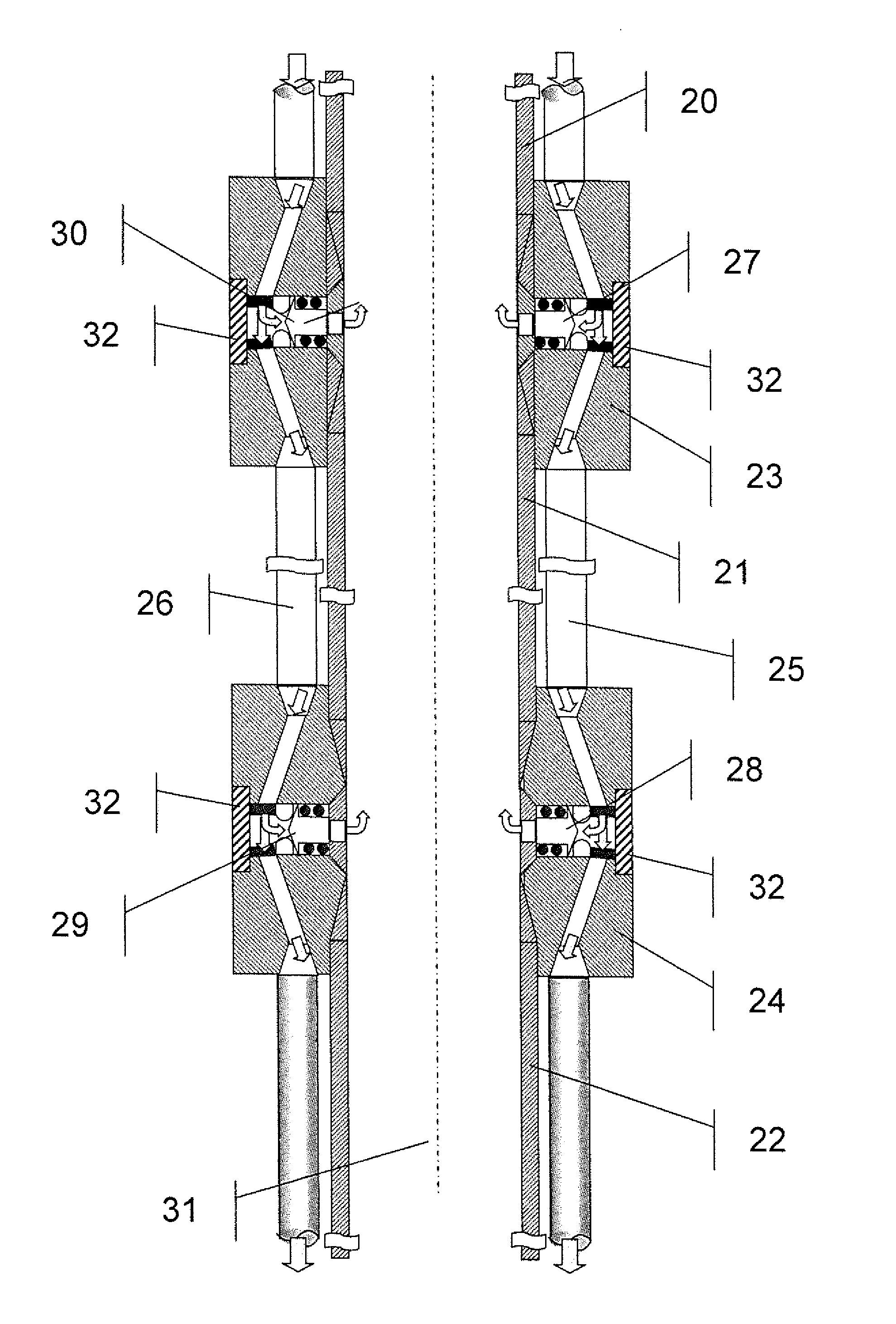
[0031]The invention is explained in more detail below using preferred exemplary embodiments with reference to figures of a drawing. Here:

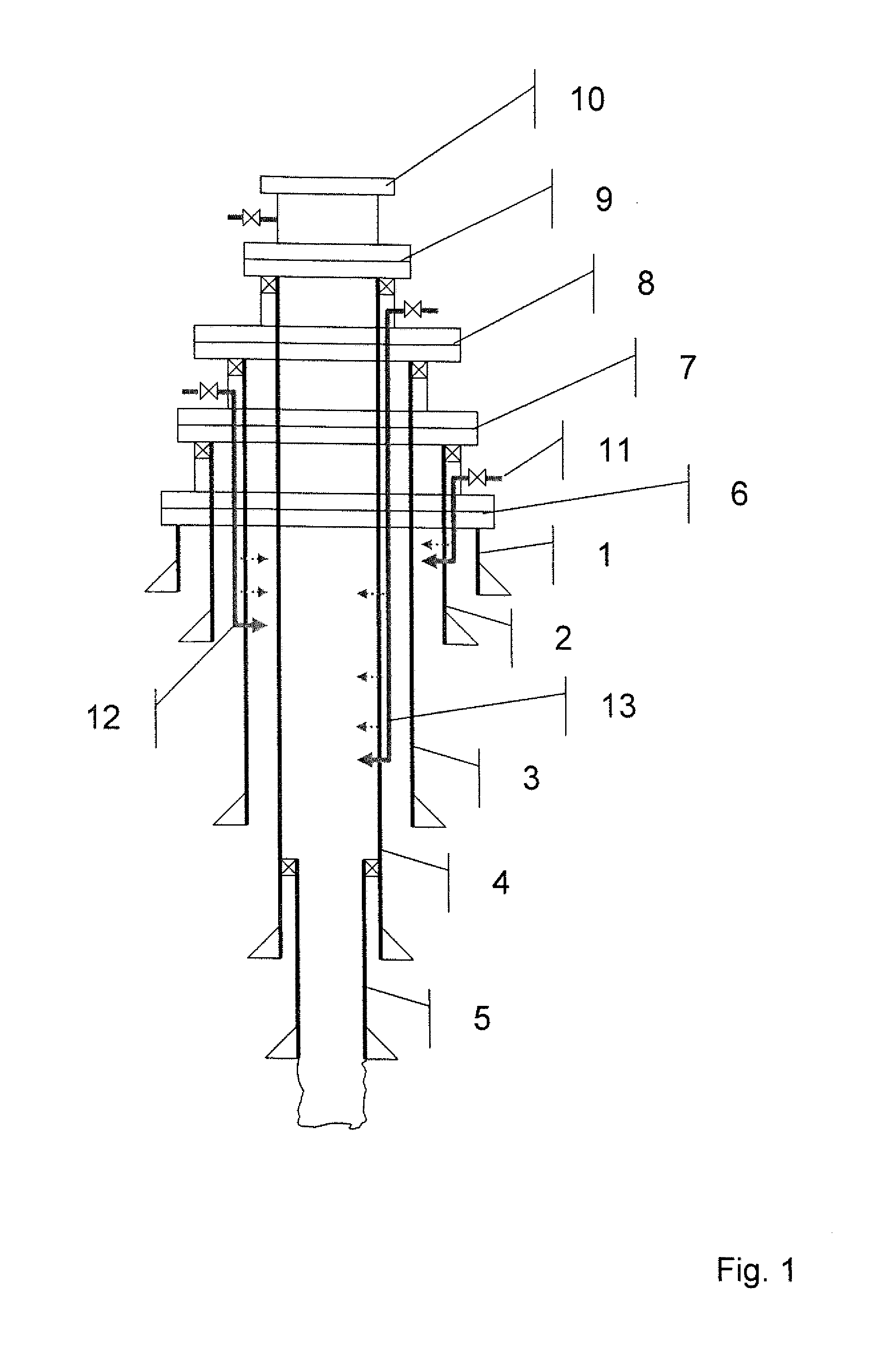
[0032]FIG. 1 shows a schematic diagram of a pipe string design with a plurality of pipe strings of a geological drill hole,

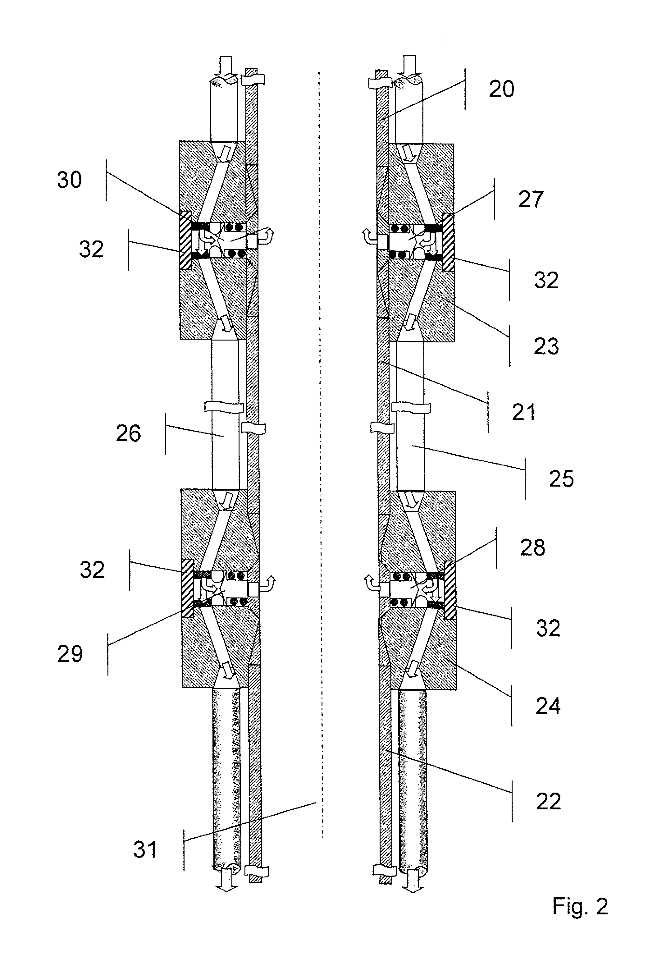
[0033]FIG. 2 shows a schematic diagram of an arrangement with three pipe string elements which are connected with connecting bushings, and

[0034]FIG. 3 shows a schematic diagram of an arrangement with three pipe strings of a geological drill hole, which are cemented in.

[0035]FIG. 1 shows a schematic diagram of a pipe string design of a geological drill hole. There is a plurality of pipe strings 1, . . . , 5, which are each cemented in, shown with different diameters. The pipe strings 1, . . . , 5 are terminated at the top with the aid of associated flanges 6, . . . , 10. Three pipe strings 2, 3, 4 are provided on the outside with a respective fluid supply line 11, 12, 13 via which a fluid, in particular a gas, can be fed into th...


PUM


Abstract

The invention relates to an apparatus for a pipe string of a geological drill hole, with a pipe string element and a fluid supply line which is arranged outside the pipe string element, extends along the pipe string element and is connected to a fluid injection device on the pipe string element, by means of which a fluid supplied through the fluid supply line can be introduced into an inner space of the pipe string element. The invention furthermore relates to a pipe string of a geological drill hole, in particular of a geothermal drill hole, a method for operating a geological drilling machine and a method for producing a pipe string for a geological drill hole.

Description

[0001]The invention is in the field of technologies for geological boreholes. The invention relates in particular to an apparatus for a pipe string of a geological drill hole, a pipe string of a geological drill hole, a method for operating a geological drilling machine and a method for producing a pipe string for a geological drill hole.BACKGROUND OF THE INVENTION[0002]Geological bores are needed and constructed in connection with various applications. These include for example production of oil or natural gas. The production of geological bores to great depths is however also necessary in connection with geothermal energy. Geothermal energy involves using the energy stored in the earth, insofar as it can be obtained.[0003]Appropriate systems in the form of drilling and production devices have been proposed for the different applications for geological bores, namely in particular the construction of a geological drill hole and the subsequent production of a fluid through the drill ...

Claims


Application Information

Patent Timeline
IPC IPC(8): E21B7/00E21B19/00
CPCE21B17/1035E21B43/123E21B43/122E21B21/103
Inventor PREVEDEL, BERNHARD
Owner GEOFORSCHUNGSZENT POTSDAM A CORP OF GERMANY
Learn More