
Rotary meshing engagement apparatus

Inactive Publication Date: 2012-02-02
TOYOTA JIDOSHA KK
View PDF4 Cites 23 Cited by
  • Summary
  • Abstract
  • Description
  • Claims
  • Application Information

AI Technical Summary

Benefits of technology

[0017]Moreover, even if the second engaging element is the rotational element, the detecting device can be provided even on the second engaging element side for a reasonable reason (as long as it is the rotational element, it is inevitably provided with a mechanism which can directly or indirectly derive its rotational speed (which is the value of temporal differentiation of the rotation amount), so that the effect is not reduced at all.
[0018]As described above, according to the rotary meshing engagement apparatus of the present invention, by providing a geometric relation among the displacement amount in the shaft line direction, the rotation amount of the first and second rotational elements, and the predetermined angle associated with the first and second tooth-shaped members, as an arithmetic expression, an arithmetic algorithm or the like, experimentally, experientially, theoretically, or as a result of simulations or the like in advance, it is possible to accurately estimate the displacement amount on the basis of the rotation amount and the predetermined angle, for example, by performing an arithmetic operation process according to the arithmetic expression and the arithmetic algorithm or the like provided in advanced at each time, or by referring to a map or the like stored in a proper memory device in advance. In other words, it is possible to estimate the displacement amount in the shaft line direction of the first or second engaging element without causing the increase in cost and body size.
[0019]In addition, the rotary meshing engagement apparatus of the present invention has: a first technical idea that the displacement amount in the shaft line direction is estimated on the basis of the rotation amount in the rotational direction; and a second technical idea that a correlation is provided between the displacement amount and the rotation amount by the shapes of the first and second tooth-shaped members formed in the first and second engaging elements. The technical ideas provide the effect that the displacement amount can be estimated without the increase in cost and the increase in body size, which is extremely useful in practice and which is unique to the present invention.
[0021]According to this aspect, the inclination angle to the shaft line direction defined on one engagement surface of each of the first and second tooth-shaped members changes at the plurality of stages. In this configuration, if the driving force for facilitating the displacement in the shaft line direction is constant or substantially constant, a rate of change in the relative rotation amount is changed at a position at which the inclination angle is changed, so that a reference position associated with the estimation of the displacement amount can be accurately determined. Therefore, it is possible to estimate the displacement amount, more highly accurately.
[0023]According to this aspect, the release force for biasing the first or second engaging element toward the position corresponding to the release state is always applied by the release force applying device such as a return spring. Thus, in changing the lock state to the release state, the application of the driving force associated with the driving force applying device may be stopped, and thus it is possible to save energy resources to be supplied to the driving force applying device.
[0028]According to this aspect, it is possible to substitute the driving force for the release force by using the controlling device which can adopt a form of various computer systems such as various controllers or microcomputer apparatuses, various processing units such as a single or a plurality of ECUs, which can appropriately include one or more CPUs, MPUs, various processors or various controllers, or various memory devices such as a ROM, a RAM, a buffer memory or a flash memory, and the like. Moreover, it is possible to make it certain to maintain the first and second engaging elements in the release state in proper timing, so that it is preferable.

Problems solved by technology

In the apparatus disclosed in the patent document 1, the stroke sensor is used to detect the stroke volume of engaging elements; however, in the configuration that this type of sensor is separately added, it causes an increase in cost and body size.
On the other hand, if it is attempted to avoid the increase in cost and body size, then, inevitably, it is necessary to engage the engaging elements without detecting the stroke volume, and according to circumstances, drivability decreases due to the engagement shock or noises.

Method used


Image

  • Rotary meshing engagement apparatus
  • Rotary meshing engagement apparatus
  • Rotary meshing engagement apparatus

Examples


first embodiment

Structure of Embodiment

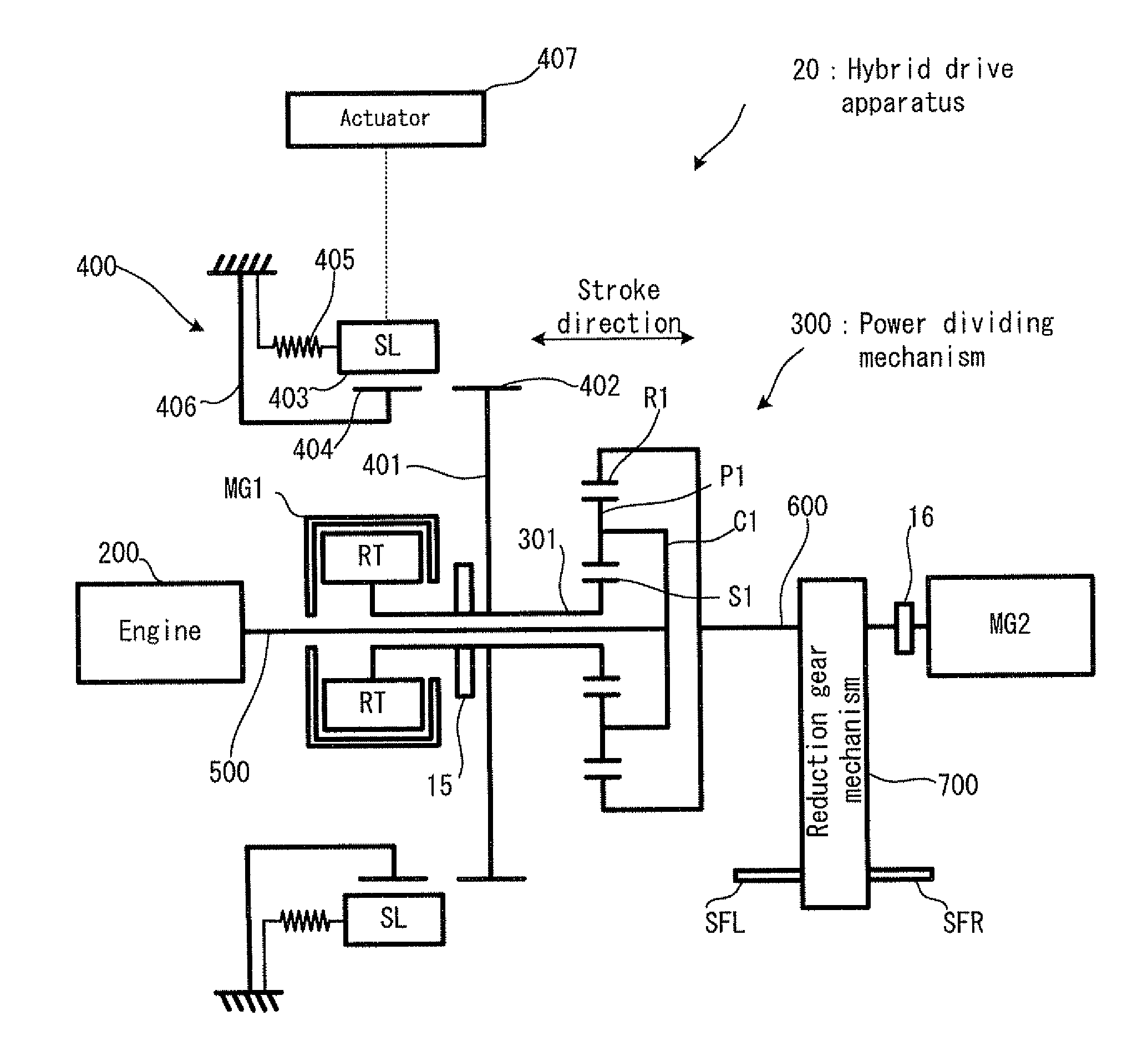
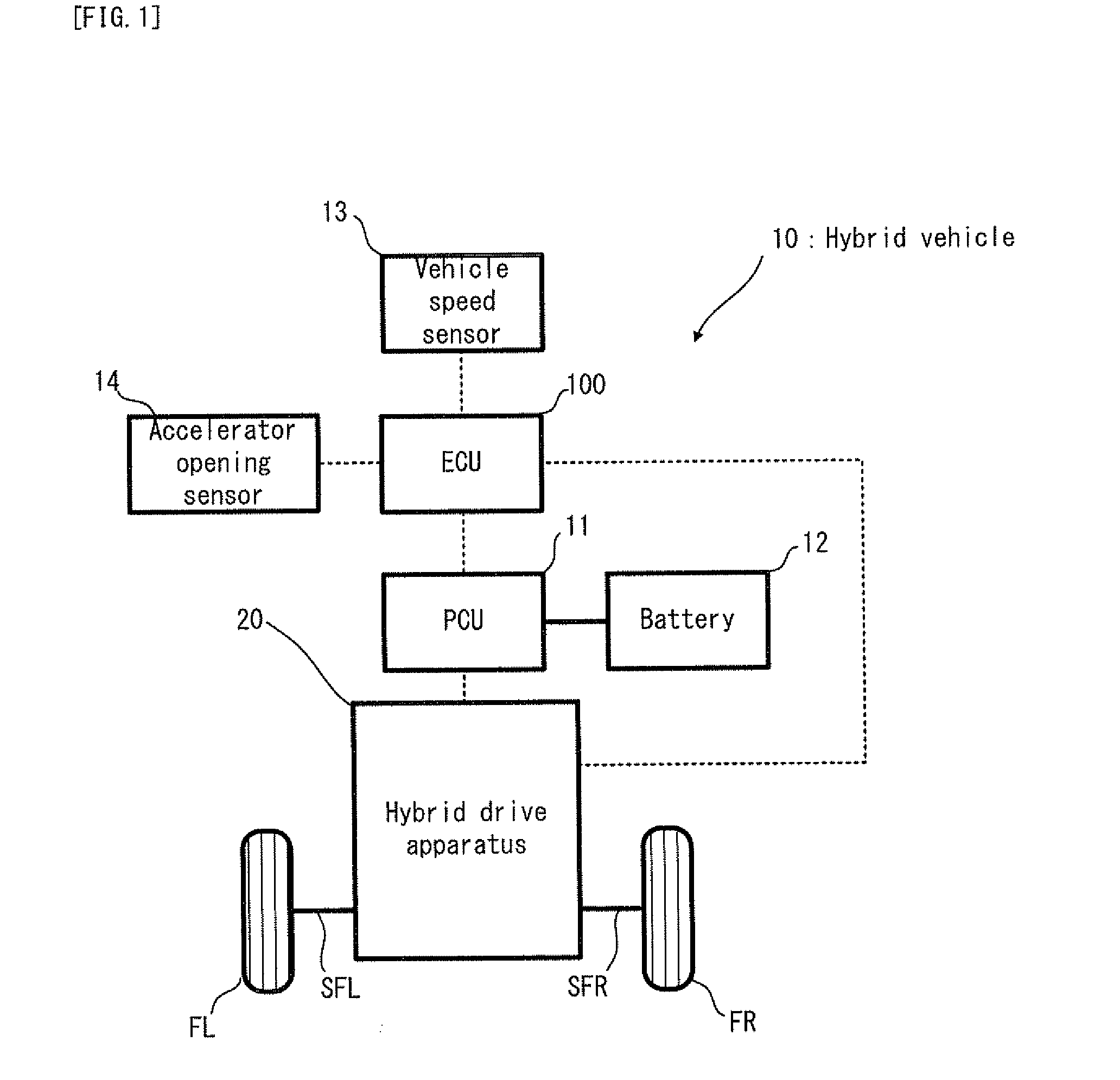
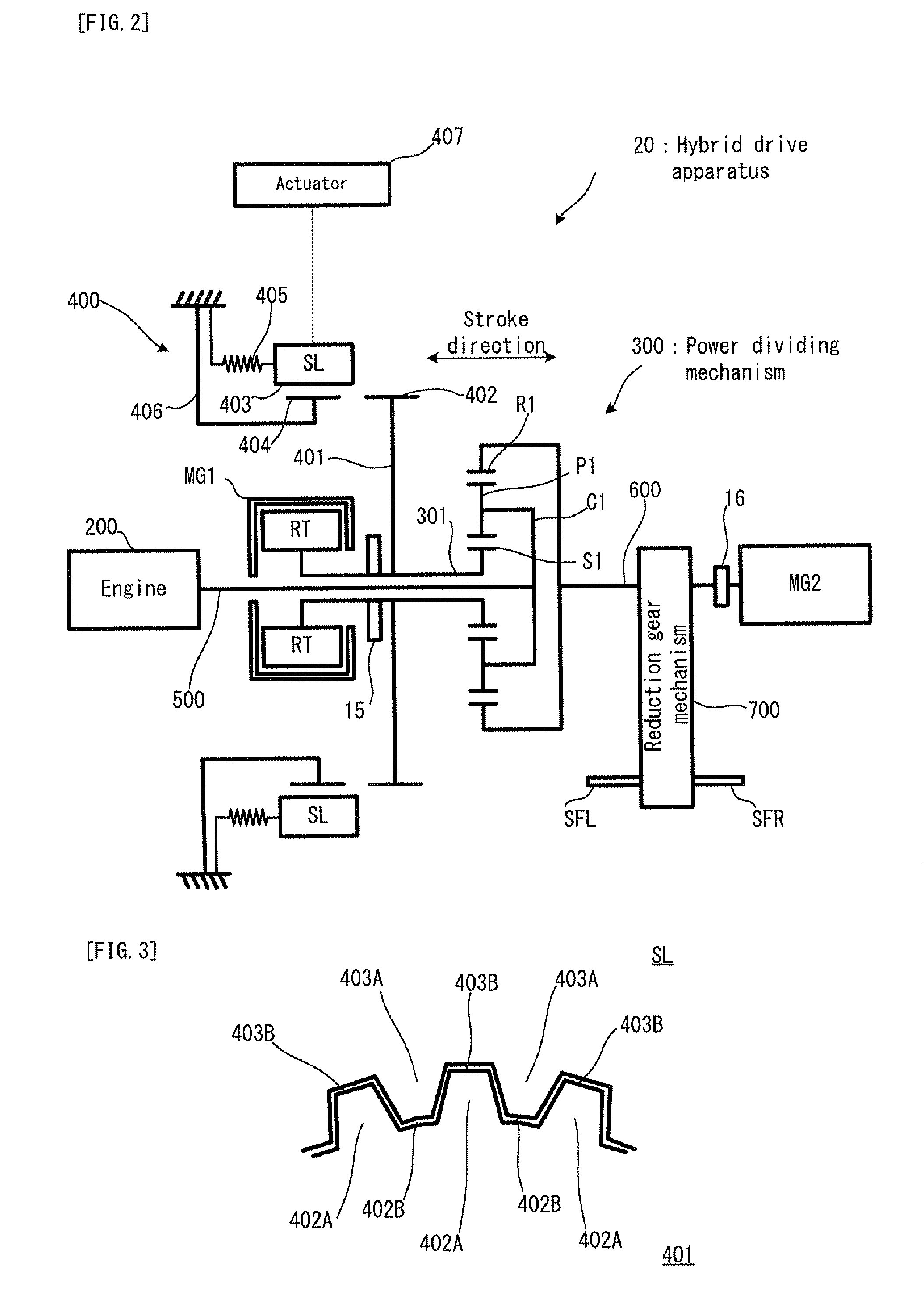
[0046]Firstly, with reference to FIG. 1, an explanation will be given on the structure of a hybrid vehicle 10 in a first embodiment of the present invention. FIG. 1 is a schematic configuration diagram conceptually showing the structure of the hybrid vehicle 10.

[0047]In FIG. 1, the hybrid vehicle 10 is one example of the “hybrid vehicle” of the present invention, provided with: an ECU 100; a PCU (Power Control Unit) 11; a battery 12; a vehicle speed sensor 13; an accelerator opening sensor 14; and a hybrid drive apparatus 20.

[0048]The ECU 100 is provided with a CPU, a ROM, a RAM and the like. The ECU 100 is an electronic control unit which can control the operations of each part of the hybrid vehicle 10. The ECU 100 is one example of the “specifying device” and the “estimating device” of the present invention.

[0049]The PCU 11 includes a not-illustrated inverter which can convert direct-current (DC) power extracted from the battery 12 to alternating-current (AC...

second embodiment

Structure of Embodiment

[0100]The shape of the dog teeth is not limited to that in the first embodiment. Now, with reference to FIG. 7, an explanation will be given on the shape of the dog teeth in a second embodiment of the present invention. FIG. 7 is a top view showing one portion of the sleeve and the hub, viewed in the direction orthogonal to the stroke direction, in the release state. Incidentally, in FIG. 7, the overlap points with FIG. 4 will carry the same reference numerals, and the explanation thereof will be omitted as occasion demands.

[0101]As shown in FIG. 7, in the second embodiment, dog teeth 403C are formed in the sleeve SL, and dog teeth 402C are formed in the hub 401. Moreover, as in the first embodiment, each of the dog teeth 403C is provided with engagement surfaces 403C1, 403C2, 403C3 and 403C4, and each of the dog teeth 402C is provided with engagement surfaces 402C1, 402C2, 402C3 and 402C4.

[0102]Now, with reference to FIG. 8, the inclination of the dog teeth i...

embodiment

Operations in Embodiment

[0106]Next, with reference to FIG. 9, the operations of the locking mechanism 400 in the second embodiment will be explained. FIG. 9 are schematic top views exemplifying the state of the sleeve SL and the hub 401 in the transition process from the release state to the lock state. Incidentally, in FIG. 9, the overlap points with FIG. 7 will carry the same reference numerals, and the explanation thereof will be omitted as occasion demands.

[0107]In FIG. 9, FIG. 9(a) shows that the engagement surface 403C2, which is the upper-side engagement surface and the backend-side engagement surface of the dog tooth 403C, engages with the engagement surface 402C1, which is the lower-side engagement surface and the backend-side engagement surface of the dog tooth 402C. In this case, if the sleeve SL is stroked in an illustrated white arrow direction, the engagement surface 402C1 is pushed away (pushed up in the figure) by the engagement surface 403C2, and the hub 401 rotates...


PUM


Abstract

In a locking mechanism provided with: a sleeve which is fixed in the circumferential direction and which can be stroked in the shaft line direction; a hub which can rotate in the circumferential direction orthogonal to the shaft line direction; and an actuator which can apply a driving force for displacing the sleeve in the shaft line direction, dog teeth are formed on the inner circumferential surface of the sleeve, and dog teeth are formed in the hub. Here, the engagement surfaces of the dog teeth are inclined at a predetermined angle with respect to the shaft line such that the hub performs relative rotation with respect to the sleeve in a process in which the sleeve is stroked in the shaft line direction. The ECU estimates the stroke volume of the sleeve on the basis of the rotation amount of the hub and the predetermined angle.

Description

TECHNICAL FIELD[0001]The present invention relates to a rotary meshing engagement apparatus including an engaging device such as an electromagnetic dog clutch device.BACKGROUND ART[0002]As this type of rotary meshing engagement apparatus, there has been suggested a control apparatus for a vehicle which adopts a dog clutch (e.g. refer to a patent document 1). According to the control apparatus for the vehicle disclosed in the patent document 1, it is described that an engagement shock can be reduced by detecting a stroke volume with a stroke sensor at the time of engagement of the dog clutch and by adjusting a phase difference.PRIOR ART DOCUMENTPatent Document[0003]Patent document Japanese Patent Application Laid Open No. 2006-083919DISCLOSURE OF INVENTIONSubject to be Solved by the Invention[0004]In the apparatus disclosed in the patent document 1, the stroke sensor is used to detect the stroke volume of engaging elements; however, in the configuration that this type of sensor is se...

Claims


Application Information

Patent Timeline
IPC IPC(8): F16D11/14F16D27/00
CPCB60K1/02Y10T477/32B60K6/445B60K6/547B60L3/0023B60L11/123B60L11/14B60L2220/14B60L2220/42B60L2240/421B60L2240/423B60L2240/441B60L2240/443B60L2270/145F16D27/118F16D48/064F16D2011/002F16D2011/008F16D2500/1022F16D2500/10462F16D2500/30408F16D2500/50607F16H2063/305Y02T10/6217Y02T10/6239Y02T10/646Y02T10/7077Y02T10/648B60K6/365F16D2500/1066F16D2500/3021F16D2500/3022F16D2500/3026F16D2500/3108F16D2500/3144F16D2500/5108F16D2500/70223F16D2500/70404F16D2500/7041B60L50/61B60L50/16Y02T10/62Y02T10/64Y02T10/7072Y02T10/70
Inventor ISHII, DAISUKEOKUWAKI, SHIGERU
Owner TOYOTA JIDOSHA KK
Learn More