Position calculation method and apparatus with GPS

a technology of position calculation and gps, applied in satellite radio beaconing, measurement devices, instruments, etc., can solve the problems of large error t, large error t, and gps receiver clock often out of synchronization with gps satellite clocks, so as to improve the detection accuracy of position and simple and accurate manner

Inactive Publication Date: 2012-02-02
HONDA MOTOR CO LTD
View PDF1 Cites 5 Cited by
  • Summary
  • Abstract
  • Description
  • Claims
  • Application Information

AI Technical Summary

Benefits of technology

[0011]It is accordingly an object of the present invention to provide GPS position calculating method and apparatus, which are able to calculate pseudoranges in a simpl

Problems solved by technology

However, the GPS receiver clock often goes out of synchronization with the GPS satellites clocks.
Thus, the GPS receiver determines the distance to each GPS satellite as a “pseudorange”, which involves clock error.
However, because the clock error Δt is significantly large, a technique has been proposed in which the clock error Δt is used as a fourth variable additional to the three variables x, y, z, in order to detect the current position of the measurement point.
All of the known techniques specified above have a limited positioning accuracy due to a large error involved in the calculated pseudorange.
The proposed methods still have drawbacks that the entire system is

Method used


Image

  • Position calculation method and apparatus with GPS
  • Position calculation method and apparatus with GPS
  • Position calculation method and apparatus with GPS

Examples


first embodiment

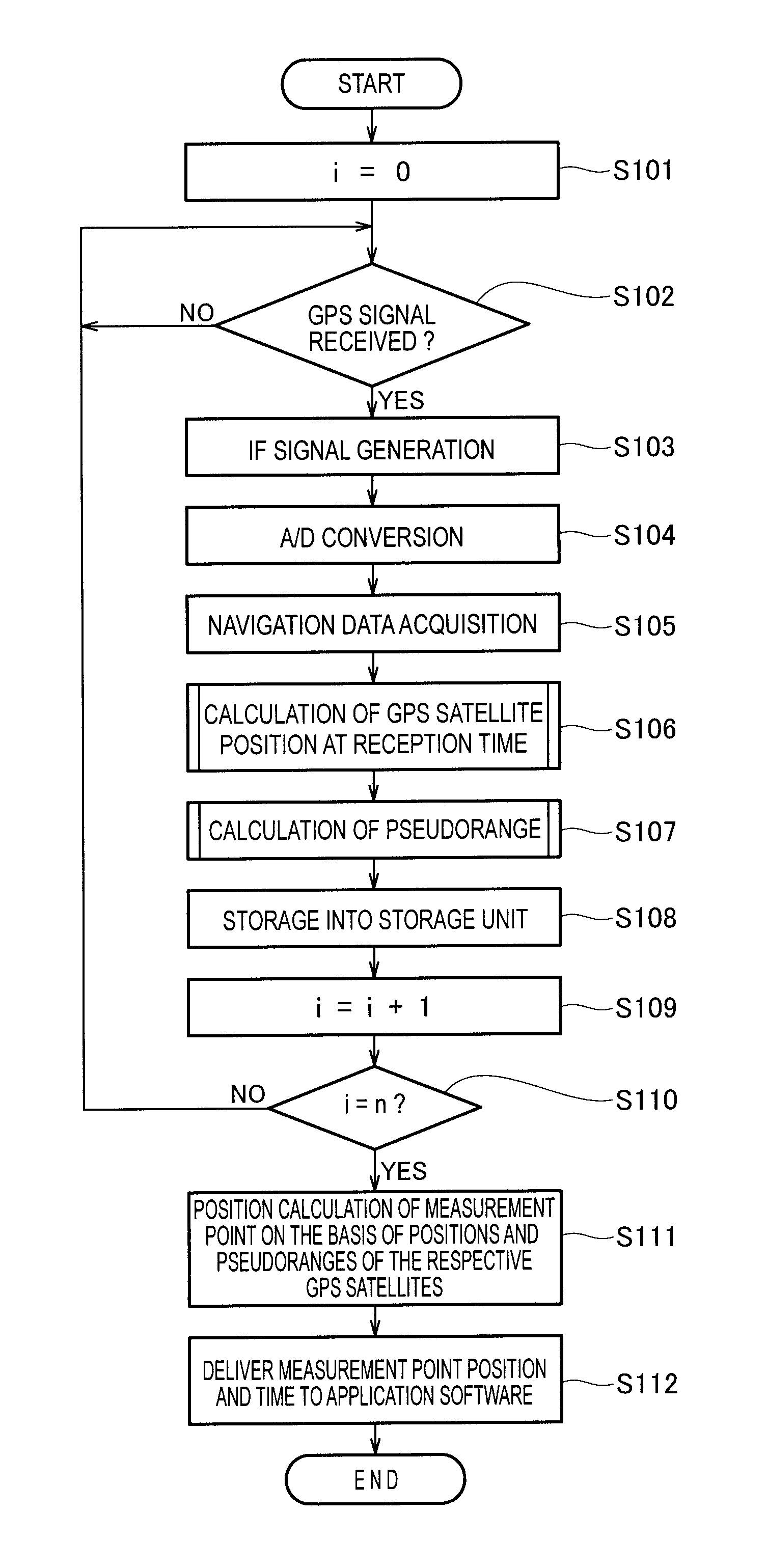
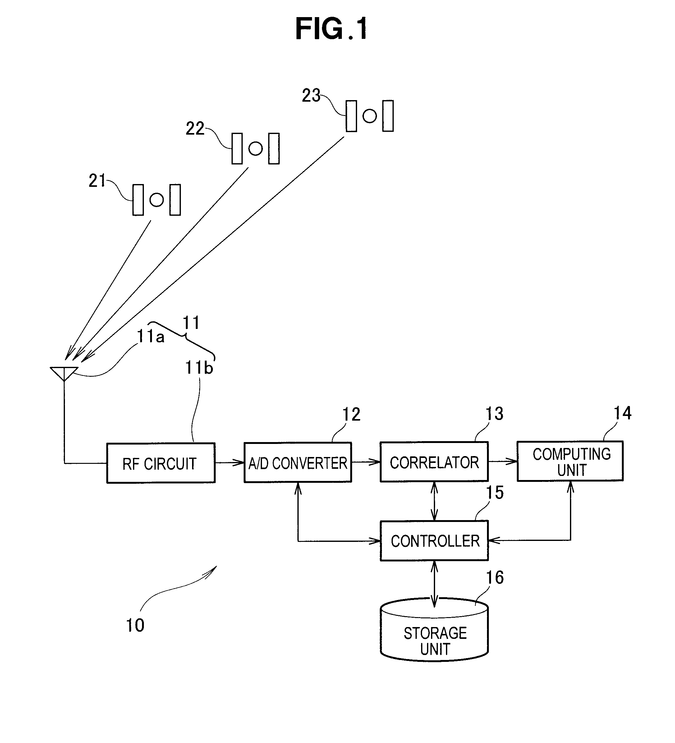
[0060]Operation of the GPS position calculating apparatus 10 according to the present invention shown in FIG. 1 will be described in detail with reference to a flowchart shown in FIG. 4. The flowchart shows a sequence of operations to be executed by the controller 15.

[0061]At step S101, the controller 15 sets a count value i of a counter assigned to the program to “0”. The counter counts the number of target GPS satellites from which signals are to be received. In the illustrated embodiment, the number “n” of target GPS satellites is three, and these three target Satellites 21, 22 and 23 are used for determining the position of a measurement point.

[0062]At step S102, the controller 15 determines as to whether a high-frequency analog signal transmitted from the first GPS satellite 21 has been received by the RF circuit 11b. If an affirmative determination is made (YES) at step S102, the control process goes on to step S103, where the RF circuits 11b down-converts the high-frequency a...

second embodiment

[0099]Operation of the GPS position calculating apparatus 10 used as GPS satellite position calculating apparatus according to the present invention will be described in detail with reference to a flowchart shown in FIG. 6. The flowchart shows a sequence of operations to be executed by the controller 15.

[0100]At step S201, the controller 15 sets a count value i of a counter assigned to the program to “0”. The counter counts the number of target GPS satellites from which signals are to be received. In the illustrated embodiment, the number “n” of target GPS satellites is three, and these three target Satellites 21, 22 and 23 are used for detecting a position of the reference point.

[0101]At step S202, the controller 15 determines as to whether a high-frequency analog signal transmitted from the first GPS satellite 21 has been received by the RF circuit 11b. If an affirmative determination is made (YES) at step S202, the control process goes on to step S203, where the RF circuits 11b d...

third embodiment

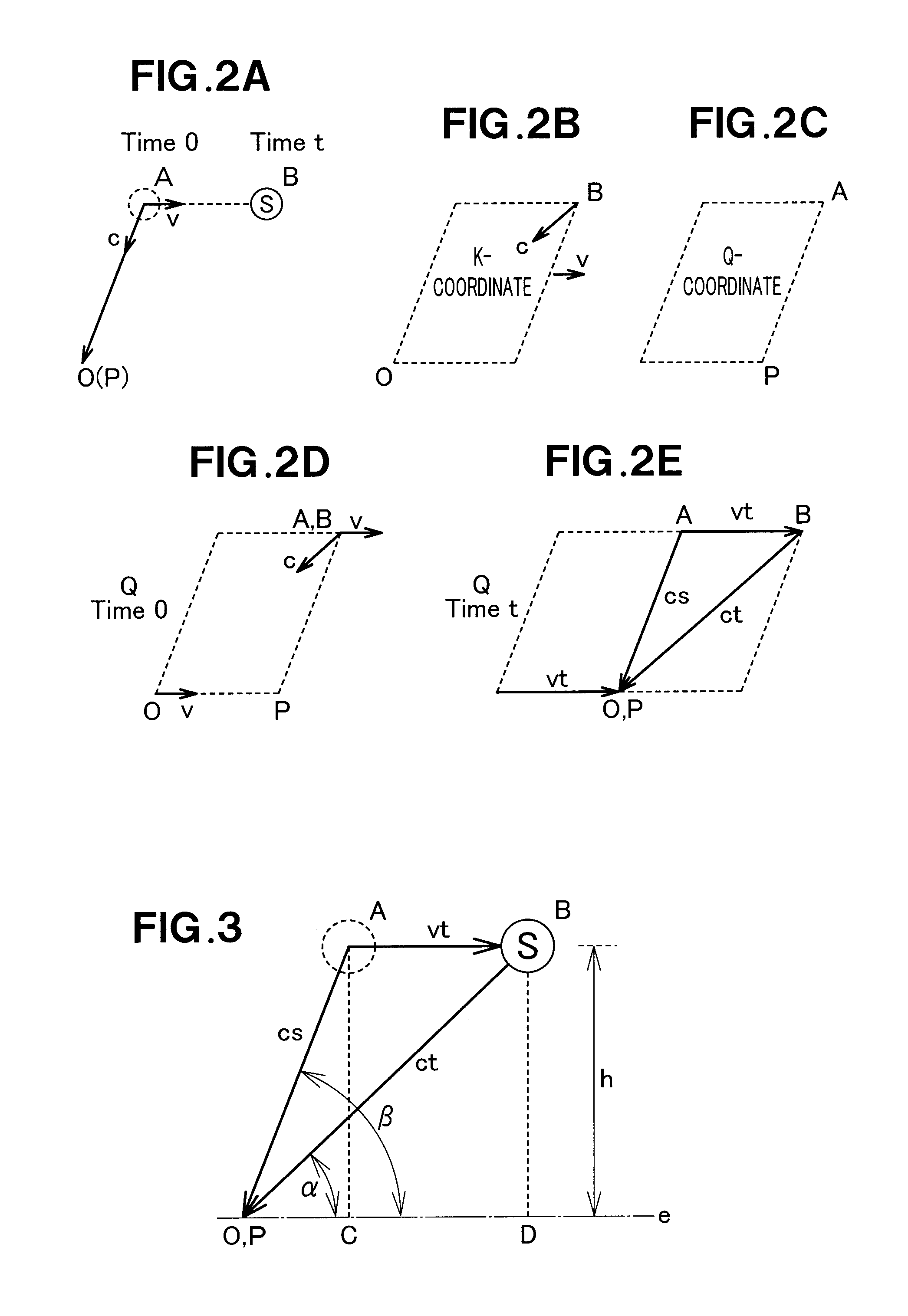
[0129]According to the GPS position calculating apparatus as used in a GPS satellite position calculating apparatus, the distance between the position B of each GPS satellite at the signal transmission time and the known position O of the reference point is used as a pseudorange in the process of calculating the position B of the GPS satellite. Unlike the conventional arrangement in which the distance between the position A of each GPS satellite at the signal transmission time and the known position O of the reference point is used as a pseudorange in the process of calculating the position of the GPS satellite, the aforesaid arrangement of the present invention is able to simplify the calculation method or procedure, increase the calculation accuracy, and eventually improve the accuracy in detecting the position of GPS satellite. Furthermore, calculation of the GPS satellite position at the signal reception time does not require observation data to be supplied from a known receiver...


PUM


Abstract

A GPS position calculating apparatus is configured to acquire orbit information from navigation data contained in signals transmitted from GPS satellites, the orbit information including a position, clock time and orbital speed of each GPS satellite at a transmission time of each signal, to calculate a position of each GPS satellite at a reception time of the same signal at a measurement point, from the acquired orbital speed and clock time, to calculate a range of a line segment connecting the calculated position of each GPS satellite with a position of the measurement point using a time difference between the transmission time and the reception time, and to calculate the position of the measurement point using the calculated range of the line segment as a pseudorange. A GPS position calculating method carried out by the apparatus is also disclosed.

Description

FIELD OF THE INVENTION[0001]The present invention relates to a method of and an apparatus for calculating the position of a measurement point on the earth or the positions of plural GPS (global positioning system) satellites by using signals received from the GPS satellites.BACKGROUND OF THE INVENTION[0002]In order to perform detection of an actual position of a GPS receiver, the GPS receiver needs to learn the distances to GPS satellites and positions of the GPS satellites. Signals transmitted from the GPS satellites are modulated and contain data called “navigation message”, which includes orbit information. The navigation message will be hereinafter referred to as “navigation data”.[0003]The GPS receiver receives navigation data from the GPS satellites and by measuring positions of the GPS satellites and the distances from the GPS satellites to a measurement point, the GPS receiver detects a position of the measurement point, which is constituted by a movable object, such as an a...

Claims


Application Information

Patent Timeline
IPC IPC(8): G01S19/42
CPCG01S19/42
Inventor SHIOMI, KAZUYUKI
Owner HONDA MOTOR CO LTD
Why Eureka
Try Eureka