Self ligating bracket system

a self-ligating, bracket technology, applied in the field of orthodontic bracket systems, can solve the problems of increasing the difficulty of orthodontic professionals using steel ligatures or elastomeric ligatures associated with conventional brackets, increasing the cost of specific procedures, and increasing the difficulty of orthodontic professionals using ligatures. , to achieve the effect of convenient replacement, improved fatigue resistance, and convenient orthodontists

Active Publication Date: 2012-02-02
LOPES ALEXANDRE GALLO
View PDF6 Cites 39 Cited by
  • Summary
  • Abstract
  • Description
  • Claims
  • Application Information

AI Technical Summary

Benefits of technology

[0029]A convertible feature of the bracket allows the orthodontic professional to have the option of continuing to use the bracket as the treatment progresses towards the end without having to change brackets. The convertible feature also facilitates the orthodontist to use the instruments that the orthodontist normally uses every day during routine or normal procedures in order to convert the bracket. In addition to the convertability aspect, the clip on the inventive self ligating bracket allows the clip to easily be replaced in a simple, one step operation without having to remove or change the bracket.
[0030]Moreover, the inventive self ligating orthodontic convertible bracket includes a shape memory sliding clip member having improved fatigue resistance that withstands numerous opening and closing cycles and remains active and operational in the aggressive mouth environment throughout the orthodontic treatment. Preferably, the shape memory clip is manufactured from a Ni / Ti superelastic alloy by die stamping, chemically-etching, laser cut, or any other now-known or later developed process and provides such advantages as increased strength, flexibility, resilience, durability, reliability, shape memory, and the like.

Problems solved by technology

The use of steel ligatures or elastomeric ligatures associated with conventional brackets presents new difficulties and concerns.
For example, the placement of steel ligatures is a time consuming operation that can lead to motion repetitive injuries to the orthodontic professional.
Moreover, there are considerable costs associated with the specific procedures required when using the set of sterilized instruments that are dedicated to the placement of the bracket on the tooth.
Also, elastomeric ties, although easier to place around the bracket than the previously used ties, deteriorate fairly rapidly within the mouth of the patient, absorb water, and accumulate excess plaque, thereby leading to an undesirable condition of the periodontum, such as inflammation.
Both ligating methods, i.e., the methods which use steel ligatures and elastomeric ties, suffer from the concern of high friction forces being applied to the binary bracket / archwire once normal forces are applied, which press the archwires against the bottom of the slot and prevent the working energy that is carried by the archwire from being applied to the tooth movement.
The restrictive force, independent of the treatment methodology or technique used, results in an increase in the frequency in which the archwire must be changed, as well as higher force levels being applied from the archwire to the bracket.
A difficult task in choosing the archwire that is used to move teeth is the predictability of the effective force that will be delivered by the archwire to the teeth.
Also, sometimes, the steel and elastomeric ligatures bend the archwires beyond their elastic properties, resulting in notching of the wire or plastically deforming the wire in a manner that results in a permanent bend.
Clinical modifications or placement of more conventional brackets becomes a requirement as treatment proceeds, resulting in an increase in material cost and time consuming procedures in the office.
Further, self ligating brackets include moving parts that become distorted, warped or disengaged, thereby compromising the pace of treatment.
However, most brackets have complex designs, and / or incorporate features that require prohibitively expensive machining operations or include a plurality of separate parts, which in turn increases the number of failure modes for such brackets.
The complexity in design and manufacturing processes for orthodontic self ligating brackets has driven prices exceedingly above the costs of a conventional bracket and without providing the option of converting the bracket when needed or replacing the clip in the event of breakage or malfunctioning.

Method used


Image

  • Self ligating bracket system
  • Self ligating bracket system
  • Self ligating bracket system

Examples


first embodiment

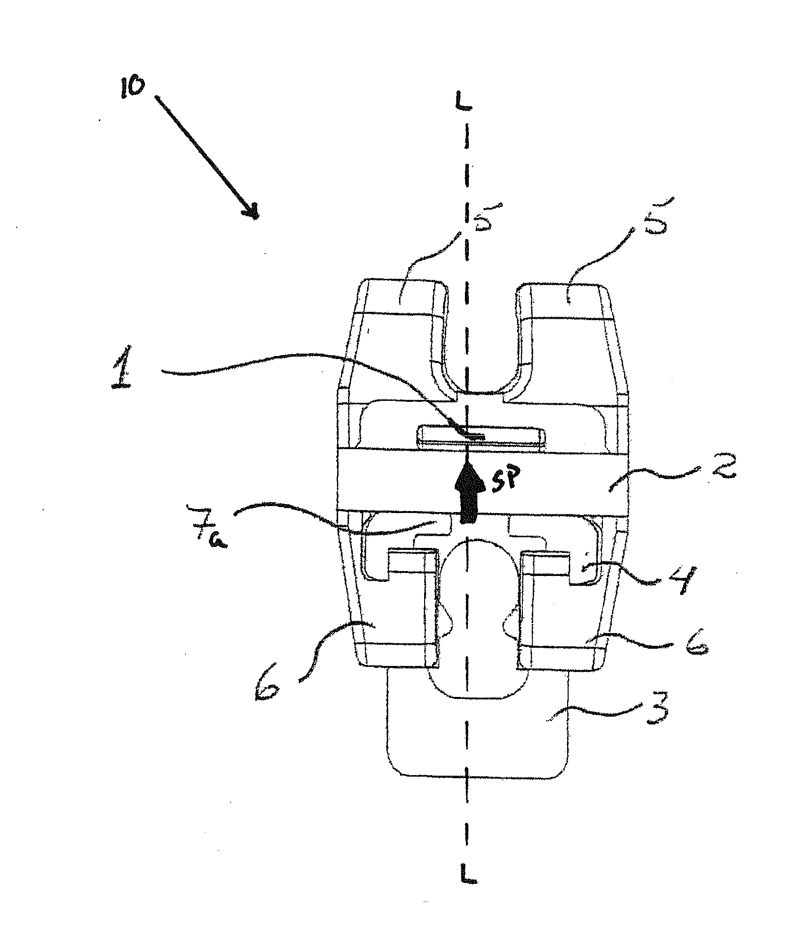
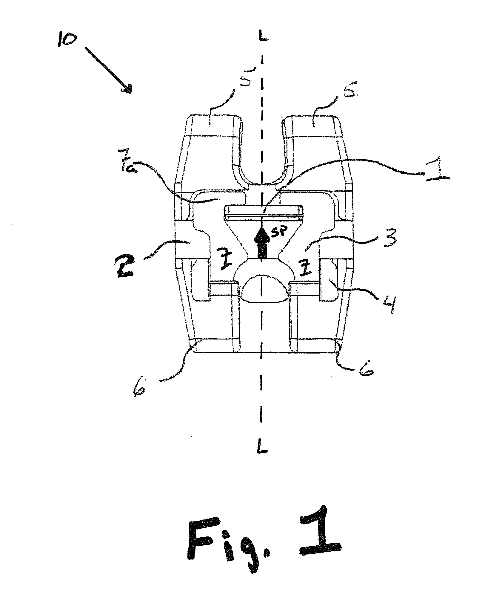
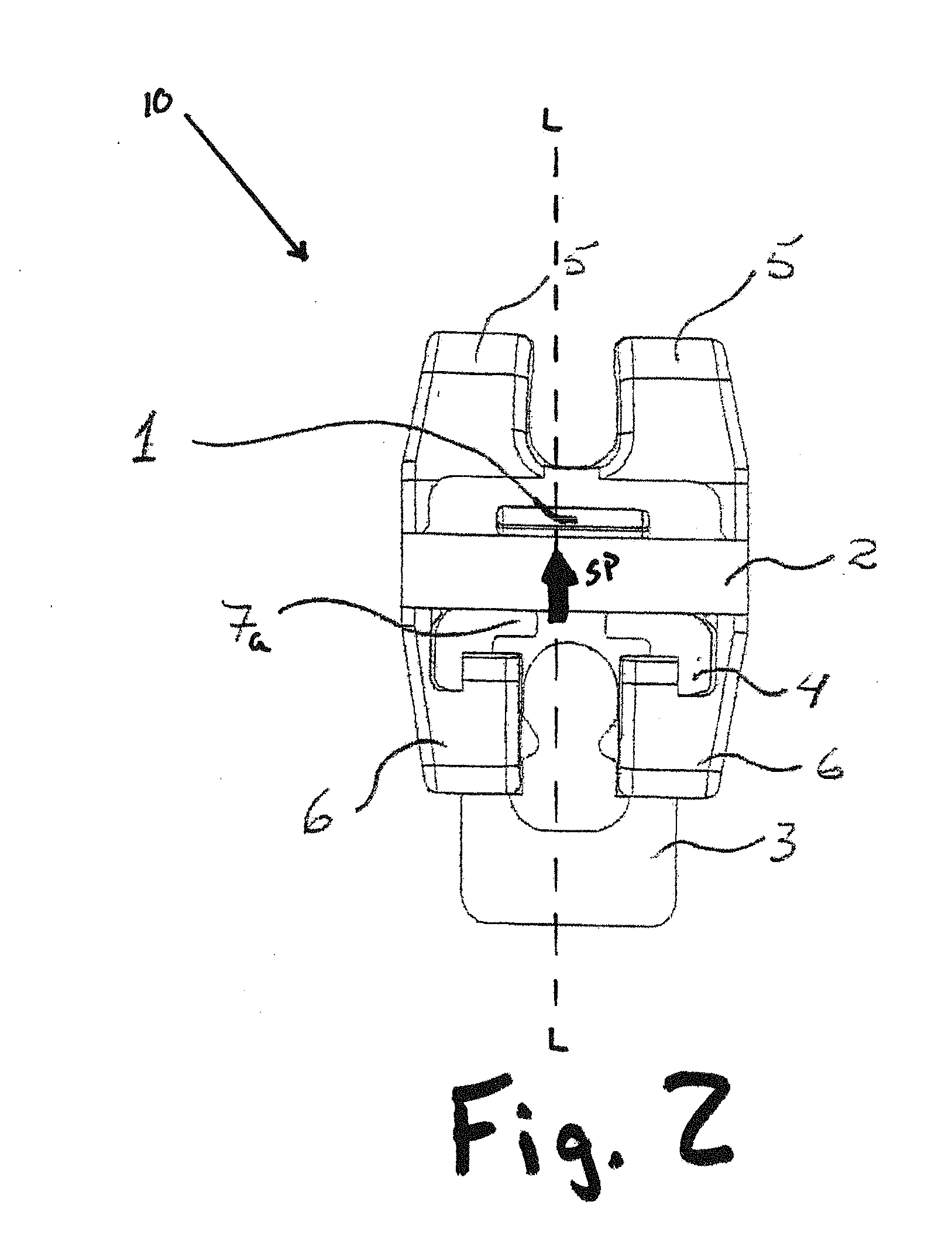
[0059]FIG. 1 illustrates a plan view of a self ligating orthodontic bracket 10 according to the present invention. The bracket 10 includes a bracket or housing 4 for attachment to the surface of a tooth, an archwire slot 2 defined by the housing 4 and configured to receive therein an archwire AW (FIG. 5), and a slidable ligating member or clip 3, illustrated in the closed or locked position, which retains the archwire AW in the archwire slot 2. The bracket 10 further includes a pair of upper tie wings 5 separated from a pair of opposing lower tie wings 6 by the archwire slot 2 defined therebetween.

[0060]It should be noted that the bracket 10 described herein, as well as any of the other embodiments of the inventive brackets, may have a base or lower surface configured to have a compound radius which may better adapt to the surface of the tooth.

[0061]Moreover, in the first embodiment as well as any of the later discussed embodiments, at least one of the upper tie wings 5 and the lowe...

second embodiment

[0070]FIG. 7 illustrates a plan view of a self ligating orthodontic bracket 110 according to the present invention.

[0071]The bracket 110 includes a self ligating orthodontic bracket or housing 14 for attachment to the surface of a tooth, an archwire slot 12 defined by the housing 14 and configured to receive therein the archwire AW, and a slidable ligating member or clip 13 illustrated in the closed or locked position which retains the archwire AW in the archwire slot 12. The bracket 110 further includes a pair of upper tie wings 15 separated from a pair of opposing lower tie wings 16 by the archwire slot 12 defined therebetween.

[0072]The clip 13 is configured to travel within the slide path SP defined by the upper and lower ties wings 15 and 16, respectively, in a direction that extends from the lower tie wings 16 to the upper tie wings 15 and which is transverse relative to the direction in which the archwire slot 12 extends. The clip 13 is preferably manufactured from a shape mem...

third embodiment

[0084]FIG. 13 illustrates a perspective view of a self ligating orthodontic bracket 210 according to the present invention.

[0085]The bracket 210 includes a bracket base 110a for attachment to the tooth surface, an archwire slot 102 configured to receive therein an archwire AW, and a slidable ligating member or clip 103 which retains the archwire AW in the archwire slot 102. The clip 103, like clips 3 and 13 of the first and second embodiments, can be selectively manipulated from the closed or locked state illustrated in FIG. 13 to the open or unlocked state, thereby exposing the archwire slot 102 extending transversely relative to the slide path SP traveled by the clip 103 in order to permit the orthodontic professional to place the archwire AW within the slot 102. The bracket 210 further includes a pair of upper tie wings 105 separated from a pair of opposing lower tie wings 106 by the archwire slot 102 defined therebetween.

[0086]The clip 103 is configured to travel along the slide...


PUM


Abstract

A self ligating orthodontic bracket system includes a bracket, a slidable ligating member and at least one wedge locking ramp. The bracket includes an archwire slot defined therein, which is configured to receive an archwire therein. The ligating member slides along a slide path defined on the bracket and which extends transverse relative to the archwire slot. The wedge locking ramp is disposed on the slide path, wherein the wedge locking ramp is configured to deflect the ligating member vertically upward and away from an upper surface of the slide path, and over the wedge locking ramp when the ligating member travels along the slide path from an unlocked position to a locked position. The archwire is securely retained in the archwire slot when the ligating member is in the locked position.

Description

BACKGROUND OF THE INVENTION[0001]1. Field of the Invention[0002]The invention relates to an orthodontic bracket system, more particularly, to a self ligating bracket that may include a shape memory sliding clip.[0003]2. Brief Description of Related Art[0004]Orthodontic treatment typically involves dental work intended to correct irregularities of the teeth or of the relation of the teeth to surrounding anatomy. The irregularities may involve malocclusions with varying degrees of severity. Examples of malocclusions include, spacing irregularities, such as excessive crowding or diastema, overbite irregularities, and underbite irregularities. Treatment of the listed exemplary irregularities, as well as others, typically involves installing braces or mechanical aids needed to reposition the teeth into an appropriate or correct orthodontic alignment.[0005]Braces conventionally include orthodontic brackets designed to be attached to either the labial or lingual surface of a tooth. The bra...

Claims


Application Information

Patent Timeline
Patent Type & Authority Applications(United States)
IPC IPC(8): A61C7/32A61C7/28
CPCA61C7/287
Inventor LOPES, ALEXANDRE GALLO
Owner LOPES ALEXANDRE GALLO
Why Eureka
Try Eureka