Drive system and motor vehicle having such a drive system

a technology of drive system and motor vehicle, which is applied in the direction of differential gearing, belt/chain/gearing, toothed gearing, etc., can solve the problems of disadvantageous generation of drag torque, increase in fuel consumption and pollution, etc., and achieve the effect of wide rotational speed range, extending the possible field of application of the drive system, and reducing the axial installation space of the drive system

Inactive Publication Date: 2012-02-09
DR ING H C F PORSCHE AG
View PDF8 Cites 21 Cited by
  • Summary
  • Abstract
  • Description
  • Claims
  • Application Information

AI Technical Summary

Benefits of technology

[0009]The electric machine that at least partially encloses the drive axle provides a very compact drive system that advantageously can be used in a small installation space. The shiftable coupling of the electric machine to the drive axle avoids continuous concurrent running of the electric machine with the drive axle and reliably prevents the generation of a disadvantageous drag torque.
[0017]The shifting device preferably has a shifting sleeve that can be displaced axially on the drive axle and has a first shifting sleeve outer toothing. The first shifting sleeve outer toothing is in operative engagement with a sun gear inner toothing of a sun gear of the second gear stage. This advantageously permits simple shifting of the drive system.

Problems solved by technology

Operation of the internal combustion engine under frequent load changes results in increased fuel consumption and emission of pollutants.
However, this arrangement is disadvantageous because the parallel arrangement of the shaft of the electric machine, the shaft of the generator and the drive shaft requires a relatively large installation space for the drive system.
Furthermore, a drag torque disadvantageously is generated when the electric machine is not in the electric motor operating mode due to the continuous connection of the electric machine to the drive axle.

Method used


Image

  • Drive system and motor vehicle having such a drive system
  • Drive system and motor vehicle having such a drive system
  • Drive system and motor vehicle having such a drive system

Examples


first embodiment

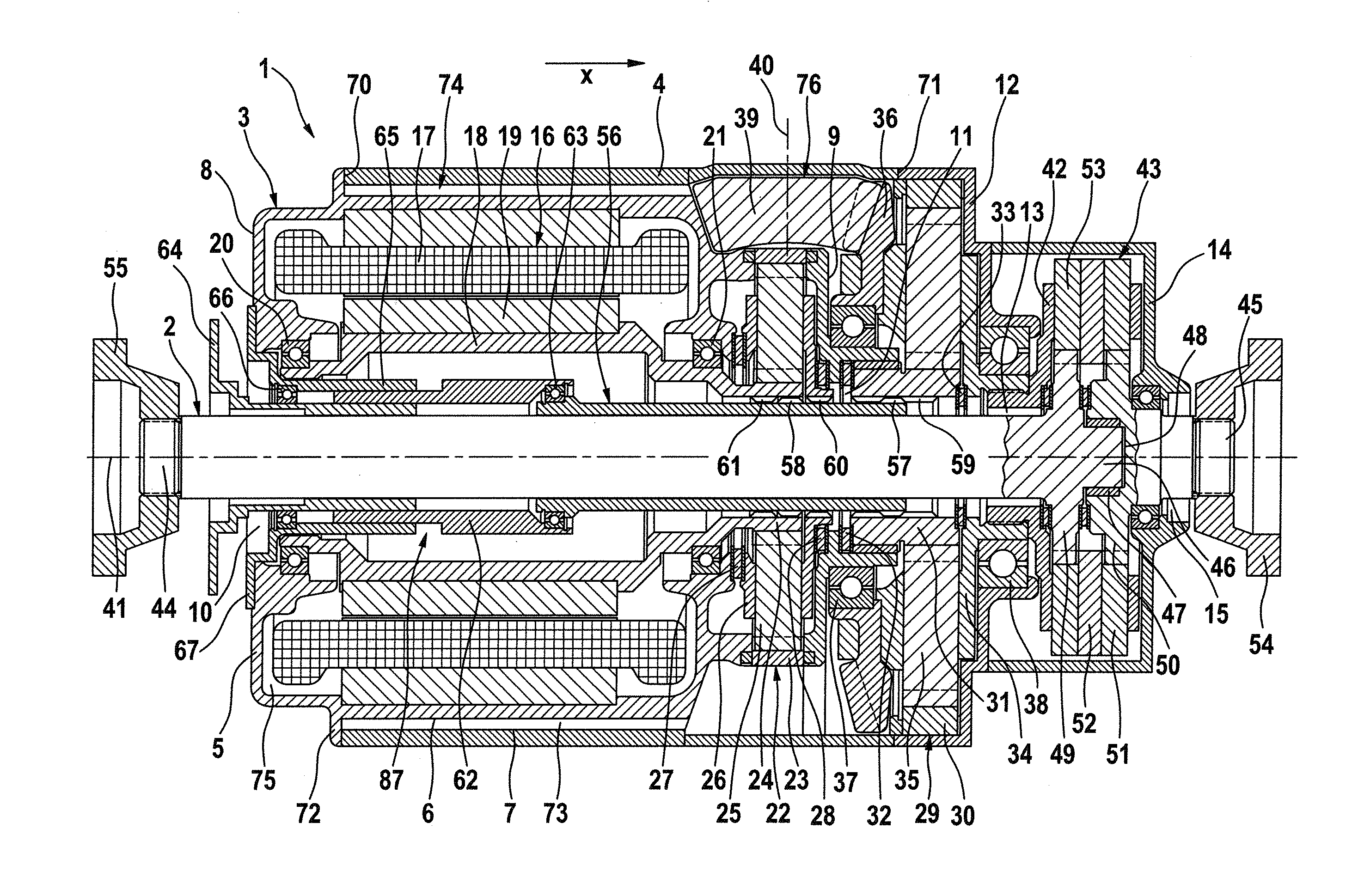
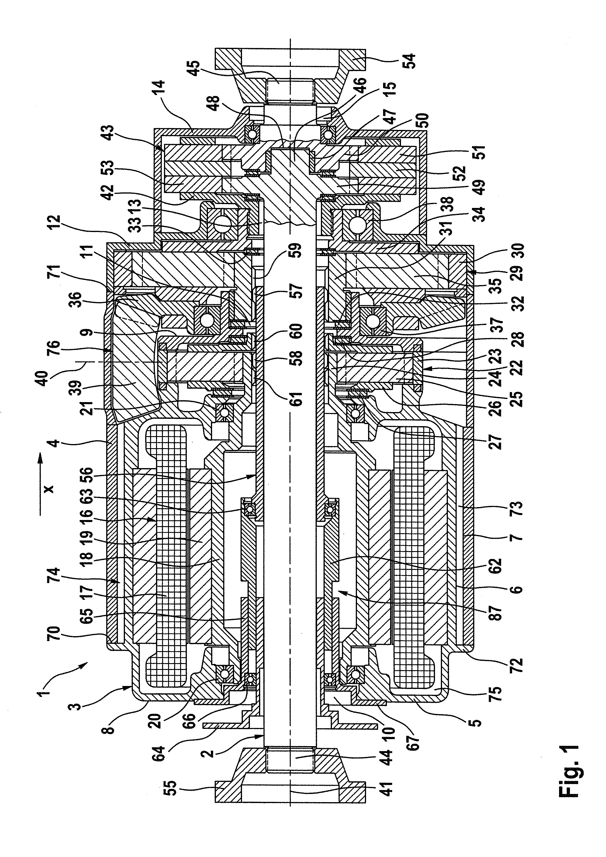
[0031]FIG. 1 illustrates a drive system 1 for a drive axle 2 of a motor vehicle. The drive axle 2 is a front axle 2 of a motor vehicle. The drive system 1 has a multi-component housing 3 connected in a rotationally fixed fashion to a load-bearing vehicle structure of the motor vehicle. The housing 3 has a hollow substantially cylindrical first housing component 4 with two annular end faces 70, 71. The first housing component 4 can be made of multiple parts. A second housing component 5 is held at least partly in the first housing component 4 and defines a barrel shape with a circumferential flange section 72 that bears against and seals to the end face 70 of the first housing component 4. The second housing component 5 is configured and held in the first housing component 4 is disposed around the drive axle 2. A tubular cavity 73 is formed between a cylindrical outer face 6 of the second housing component 5 and a cylindrical inner face 7 of the first housing component 4 and holds a ...

second embodiment

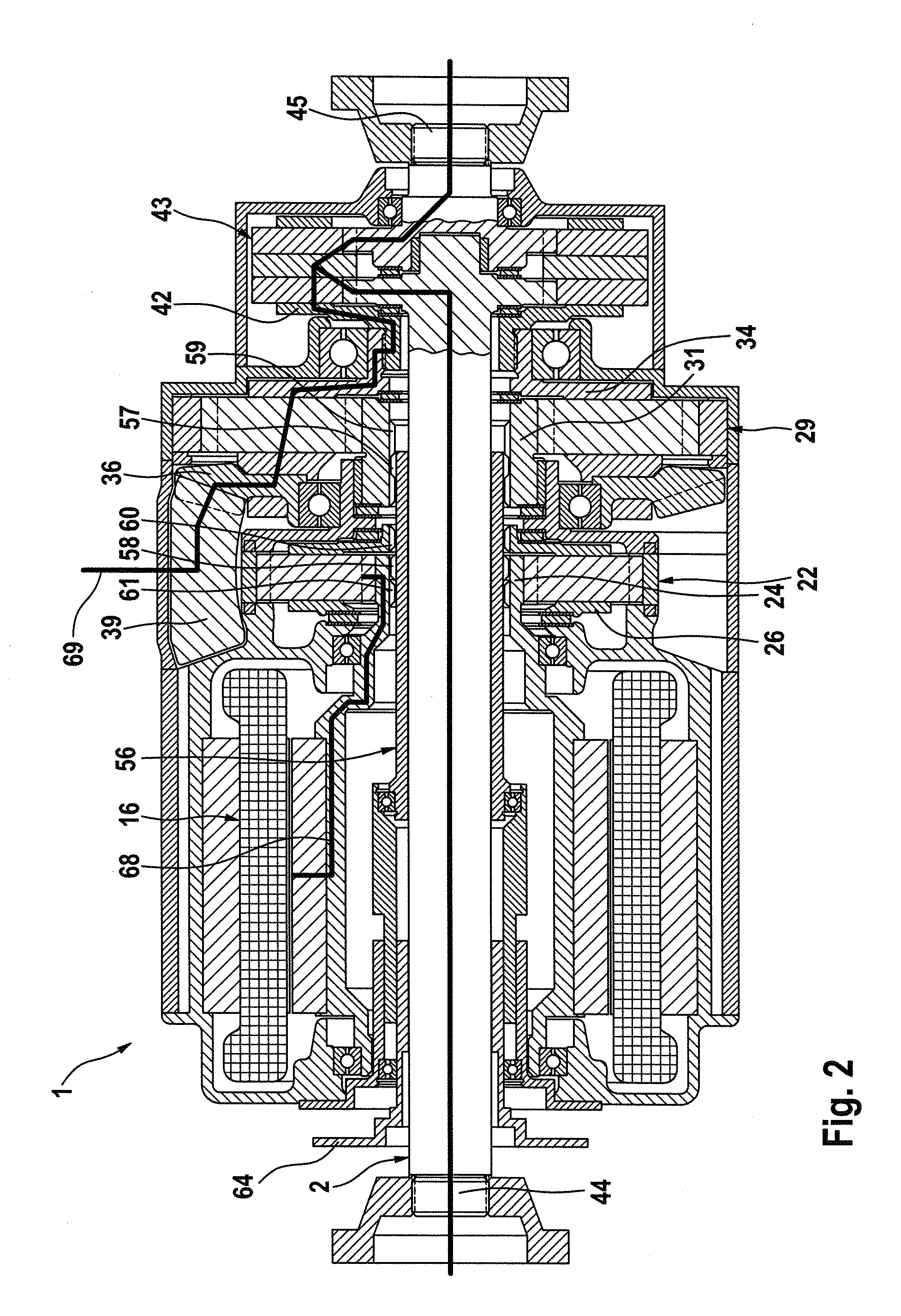
[0046]FIG. 5 illustrates a drive system 1. The drive system 1 of FIG. 5 differs from the drive system 1 of FIG. 1 essentially in that the crown gear 36 and the bevel gear 39 of FIG. 1 are not present in FIG. 2. Thus, the size of an axial installation space b of the electric machine 16 can be increased. For example, a length of 100, 120 or 140 mm can be provided as an effective length b of the stator 17. The drive systems 1 of FIGS. 1 and 5 are designed according to an identical component concept. That is to say, for the embodiment of FIG. 1 with the crown gear 36 and the bevel gear 39 and for the embodiment of FIG. 5 without the components 36, 39, the largest possible number of structurally identical components are installed, such as the gear stages 22, 29, the drive axle 2, the shifting device 87 or the differential transmission 43. The gear stages 22, 29, the drive axle 2, the shifting device 87 and the differential transmission 43 are easily replaceable prefabricated, modules 22,...


PUM


Abstract

A drive system (1) for a drive axle (2) of a motor vehicle has an electric machine (16) that at least partially encloses the drive axle (2) and that is capable of driving the drive axle (2). The electric machine (16) is coupled in a shiftable fashion to the drive axle (2) or is decoupled therefrom.

Description

CROSS REFERENCE TO RELATED APPLICATION[0001]This application claims priority under 35 USC 119 to German Patent Appl. No. 10 2010 036 884.9 filed on Aug. 6, 2010, the entire disclosure of which is incorporated herein by reference.BACKGROUND OF THE INVENTION[0002]1. Field of the Invention[0003]The invention relates to a drive system for a motor vehicle and to a motor vehicle having such a drive system. The invention can be applied to any motor vehicle, but will be described with respect to a passenger motor vehicle.[0004]2. Description of the Related Art[0005]A hybrid vehicle generally has a hybrid drive system with plural drive units, such as an internal combustion engine and an electric machine. A parallel hybrid drive system generally is used in a hybrid vehicle to generate the highest possible energy efficiency level. The parallel hybrid drive system permits the electric machine and the internal combustion engine to apply torque to a transmission either alternately or cumulatively...

Claims


Application Information

Patent Timeline
Patent Type & Authority Applications(United States)
IPC IPC(8): B60K1/00F16H48/12F16H48/06
CPCB60K2001/001B60K1/00B60K17/24F16H1/28B60K17/22
Inventor FUECHTNER, MARTINSINGER, SIMON
Owner DR ING H C F PORSCHE AG
Why Eureka
Try Eureka