Modular Junction Box for a Photovoltaic Module

a photovoltaic module and junction box technology, applied in the direction of photovoltaics, electrical apparatus, casings/cabinets/drawers of electrical appliances, etc., can solve the problems of conductive foil deformation, inability to open the junction box, and often impossible replacement or upgrading of pcbs

Inactive Publication Date: 2012-02-09
TE CONNECTIVITY CORP
View PDF6 Cites 152 Cited by
  • Summary
  • Abstract
  • Description
  • Claims
  • Application Information

AI Technical Summary

Benefits of technology

[0008]In one embodiment, a junction box for electrically connecting a photovoltaic (PV) module to a power distribution system is provided. The PV module has a plurality of conductors for electrically connecting the PV module to the junction box. The junction box includes a housing having a mounting side configured to be mounted on the PV module and a power transfer structure mounted within the housing. The power transfer structure includes a plurality of conductive connectors and a transfer interface. Each of the conductive connectors forms an electrical interface to the PV module. The transfer interface couples the junction box to the power distribution s

Problems solved by technology

More specifically, during installation of the PCB, inserting the PCB contact into the housing contact causes the conductive foil to deform.
Frequently, opening the junction box is not feasible, as some conventional junction boxes are welded shut or are glued shut with epoxy or are an integral part of the PV module.
Therefore, in the event of a failure, such as resulting from a problem on the PCB within the junction box, replacing or upgrading that PCB is often impossible without destroying the junction box and/or the PV module.
In other instances, some junction boxes, even if able to be opened, are fully potted with epoxy or sealant a

Method used


Image

  • Modular Junction Box for a Photovoltaic Module
  • Modular Junction Box for a Photovoltaic Module
  • Modular Junction Box for a Photovoltaic Module

Examples


Embodiment Construction

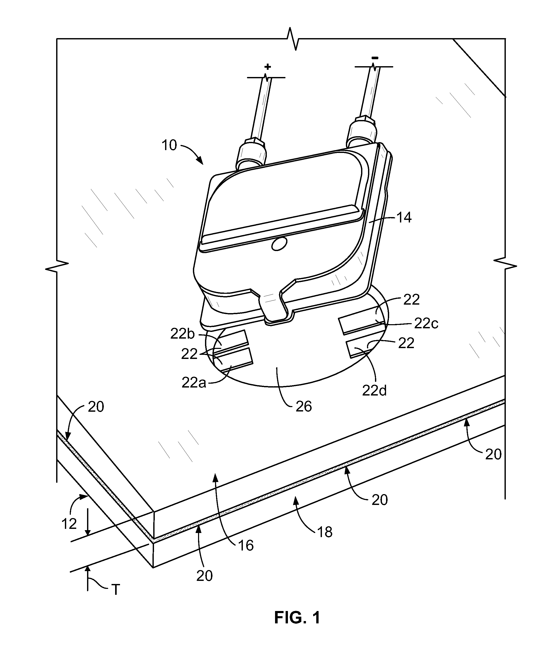
[0033]FIG. 1 is a partially exploded perspective view of an exemplary junction box and photovoltaic (PV) module assembly 10. The assembly 10 includes a PV module 12 and a junction box 14. Only a portion of the PV module 12 is shown herein. The PV module 12 includes a dielectric substrate 16, a transparent panel 18, and a plurality of PV cells 20 held between the dielectric substrate 16 and the transparent panel 18. When irradiated by a light source (such as, but not limited to, sunlight and / or the like), the PV cells 20 convert the energy of photons into electrical power. Each PV cell 20 may be any type of PV cell, such as, but not limited to, a thin film PV cell and / or a PV cell fabricated using a material such as a monocrystalline silicon, a polycrystalline silicon, a microcrystalline silicon, a cadmium telluride, and / or a copper indium selenide / sulfide material. The PV cells 20 are electrically interconnected with each other, in series and / or parallel, by an electrical foil condu...


PUM


Abstract

A junction box for electrically connecting a photovoltaic (PV) module to a power distribution system, the PV module having a plurality of conductors for electrically connecting the PV module to the junction box. The junction box includes a housing having a mounting side configured to be mounted on the PV module and a power transfer structure mounted within the housing. The power transfer structure includes a plurality of conductive connectors and a transfer interface. Each conductive connector forms an electrical interface to the PV module. The transfer interface couples the junction box to the power distribution system. The junction box also includes a user-removable control board mounted within the housing. The power transfer structure interfaces with said control board to convey power from the PV module to the control board.

Description

CROSS-REFERENCE TO RELATED APPLICATION[0001]This application claims priority to U.S. provisional patent application No. 61 / 372,065 filed Aug. 9, 2010, which is incorporated by reference in its entirety for all purposes.BACKGROUND OF THE INVENTION[0002]The subject matter described and / or illustrated herein relates generally to photovoltaic (PV) modules, and more particularly, to a junction box for interconnecting PV modules with a power distribution system.[0003]To produce electricity from solar energy, PV modules include a plurality of PV cells interconnected in series and / or parallel, according to the desired voltage and current parameters. PV cells are essentially large-area semiconductor diodes. Due to the photovoltaic effect, the energy of photons is converted into electrical power within a PV cell when the PV cell is irradiated by a light source, such as sunlight. Within a PV module, the PV cells are typically sandwiched between a transparent panel and a dielectric substrate. T...

Claims


Application Information

Patent Timeline
IPC IPC(8): H05K7/00
CPCH02S40/34Y02E10/50
Inventor GOLUBOVIC, BORISHASSAN-ALI, MUDHAFARIM, KAOCHILIMAYE, ABHIJIT
Owner TE CONNECTIVITY CORP
Why Eureka
Try Eureka