

Stimulated lighting devices
a lighting device and lighting technology, applied in lighting and heating devices, lighting source combinations, instruments, etc., can solve the problems of poor spectral quality of fluorescent light produced by existing fluorescent lighting, low energy efficiency of incandescent lighting, and eye strain and other adverse health effects
- Summary
- Abstract
- Description
- Claims
- Application Information
AI Technical Summary
Benefits of technology
Problems solved by technology
Method used
Image

Examples
example 1
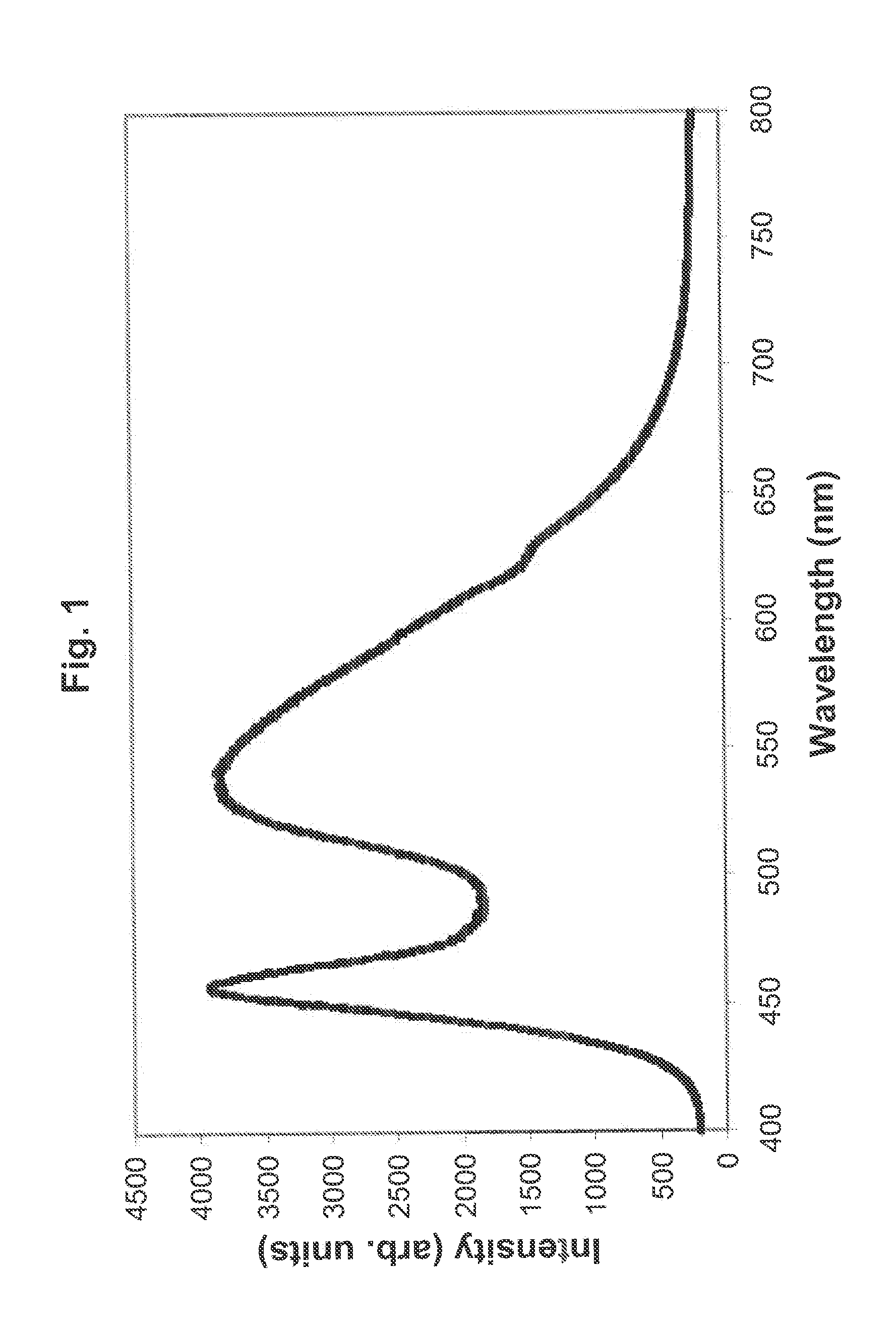
Excitation Source: Blue LED at 450-460 nm
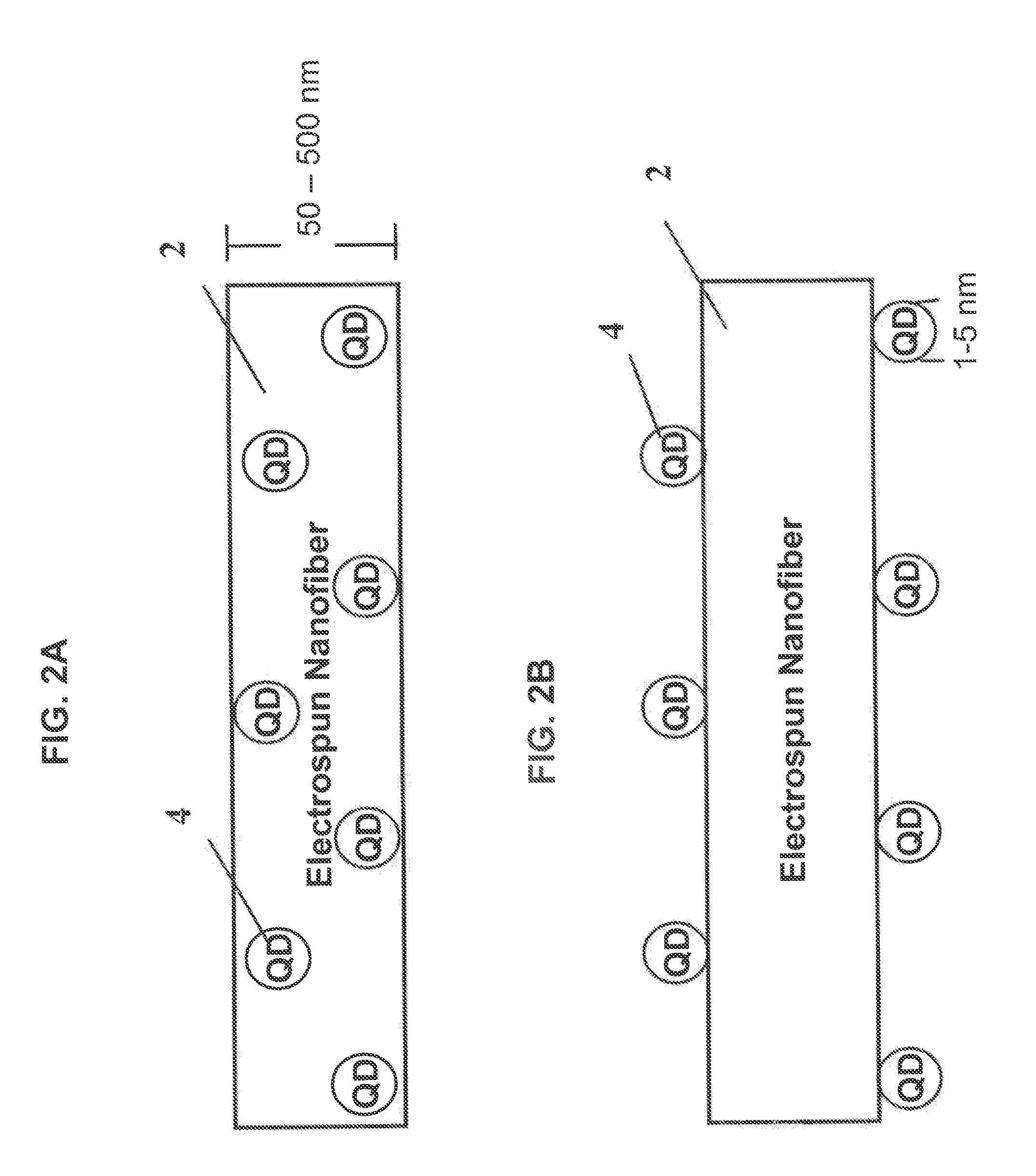
[0115]Luminescent compound: a single variety of CdSe / ZnS core shell quantum dots with particle diameter 2.6-3.2 nm (configured for yellow emission and commercially available from Evident Technologies)
[0116]Such yellow emitting quantum dots in this example are incorporated into and onto the fibers at weight percentages between 0.1% and 30% (weight quantum dots / weight fiber) with a more suitable range of weight percentage between 1% and 10% depending upon desired light output.
[0117]When packaged with the blue LED emitting at 450-460 nm, the blue light from the LED and the yellow emission from the photoluminescent fiber in this example blend to produce white light.
example 2
Excitation Source: Blue LED at 450-460 nm
[0118]Luminescent compound: Two different sizes of CdSe / ZnSe core shell quantum dots with the particle diameter of the first size being 2.4 nm (green emission) and the particle diameter of second size being 5.2 nm (red emission) (purchased from Evident Technologies).
[0119]These two sizes of luminescent quantum dots are incorporated into and onto the fibers at weight percentages between 0.1% and 30% (total weight quantum dots / weight fiber) with a more suitable range of weight percentage between 1% and 10%. The ratio of green particles to red particles incorporated into and on the fibers varies between 1:1 to 20:1 depending upon desired light output. In order to prevent undesired absorption of secondary emissions, it may be preferable to physically separate the two sizes of luminescent quantum dots. This can be achieved in one embodiment of the present invention by locating the quantum dots on separate sides of the fiber substrate or by placing...
example 3
Excitation Source: Violet LED at 408 nm
[0121]Luminescent compound: Three different sizes of CdSe / ZnSe core shell quantum dots with the particle diameter of the first size being 1.9 nm (blue emission), the particle diameter of the second size being 2.4 nm (green emission), and the particle diameter of third size being 5.2 nm (red emission) (purchased from Evident Technologies).
[0122]These three sizes of luminescent quantum dots are incorporated into and onto the fibers at weight percentages between 0.1% and 100% (total weight quantum dots / weight fiber) with a more suitable range of weight percentage between 1% and 50%. The ratio of blue particles to green particles to red particles incorporated into and on the fibers is chosen to produce light emissions with relative intensities between 1:2:3 (for “warm white” color) to 2.5:1.5:1 (for “cool white” color) depending upon desired light output. In order to prevent undesired absorption of secondary emissions, it may be preferable to physi...
PUM
| Property | Measurement | Unit |
|---|---|---|
| color rendering index | aaaaa | aaaaa |
| color rendering index | aaaaa | aaaaa |
| transmittance | aaaaa | aaaaa |
Abstract
Description
Claims
Application Information