Tem phase plate loading system

Inactive Publication Date: 2012-02-16
ACAD SINIC
View PDF5 Cites 8 Cited by
  • Summary
  • Abstract
  • Description
  • Claims
  • Application Information

AI Technical Summary

Benefits of technology

[0019]As mentioned above, the TEM phase plate loading system of the invention can transfer the phase plate into the TEM through the airlock chamber, which is disposed adjacent to the specimen section of the TEM, so that modifying the optical design of the TEM is not necessary. In other words, the phase plate loading system of the invention can be installed on any commercial TEM. Compared with the prior art, the present invention discloses an airlock chamber for pre-vacuuming the phase plate before transferring it into the TEM. Thu

Problems solved by technology

In order to develop a phase TEM that is applicable for imaging, tremendous technical difficulties have to be overcome: (1) loading the phase plate into a TEM must not degrade the functions of the TEM; (2) the phase plate needs to be positioned at the back focal plane with a high scale of precision; (3) fabrication of a reliable phase plate is technically challenging; (4) low dose imaging

Method used


Image

  • Tem phase plate loading system
  • Tem phase plate loading system
  • Tem phase plate loading system

Examples


Example

[0027]The present invention will be apparent from the following detailed description, which proceeds with reference to the accompanying drawings, wherein the same references relate to the same elements.

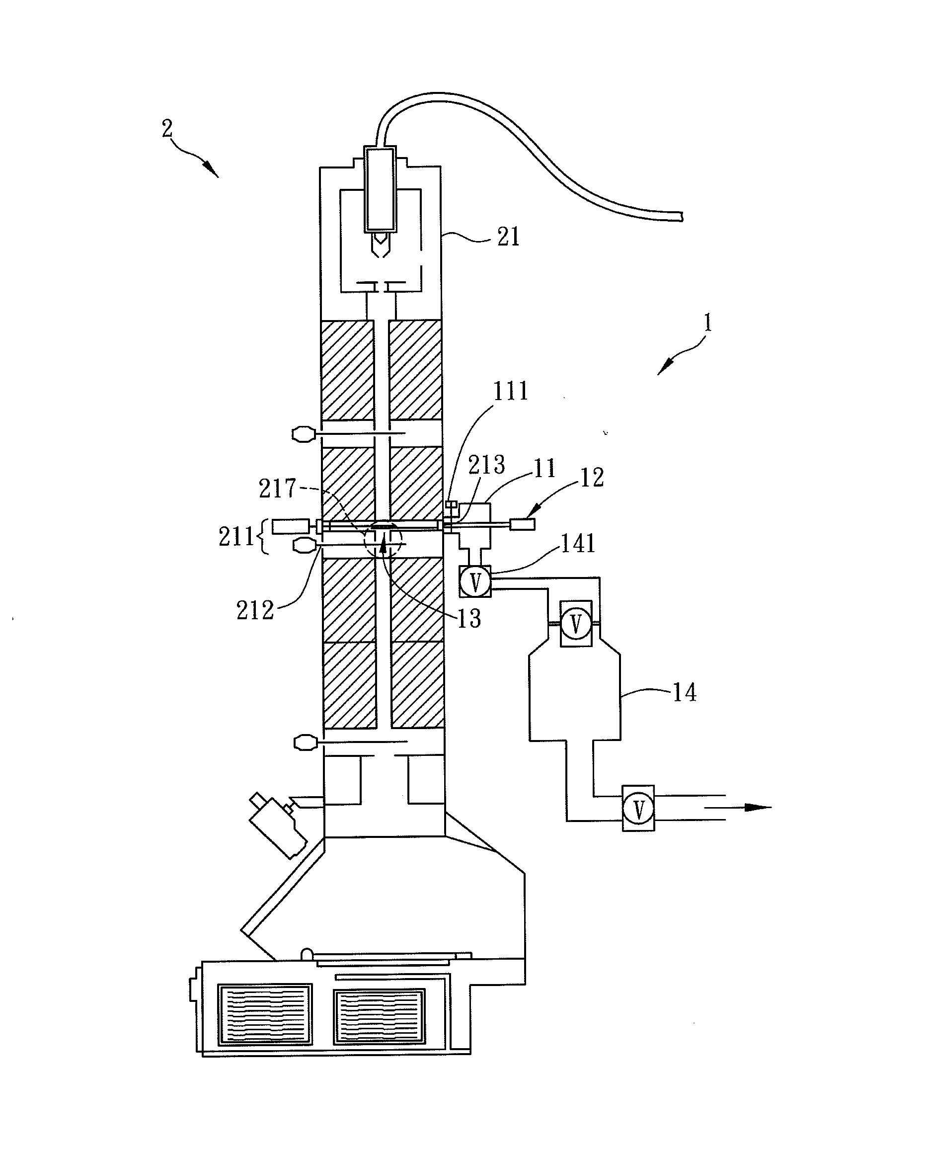
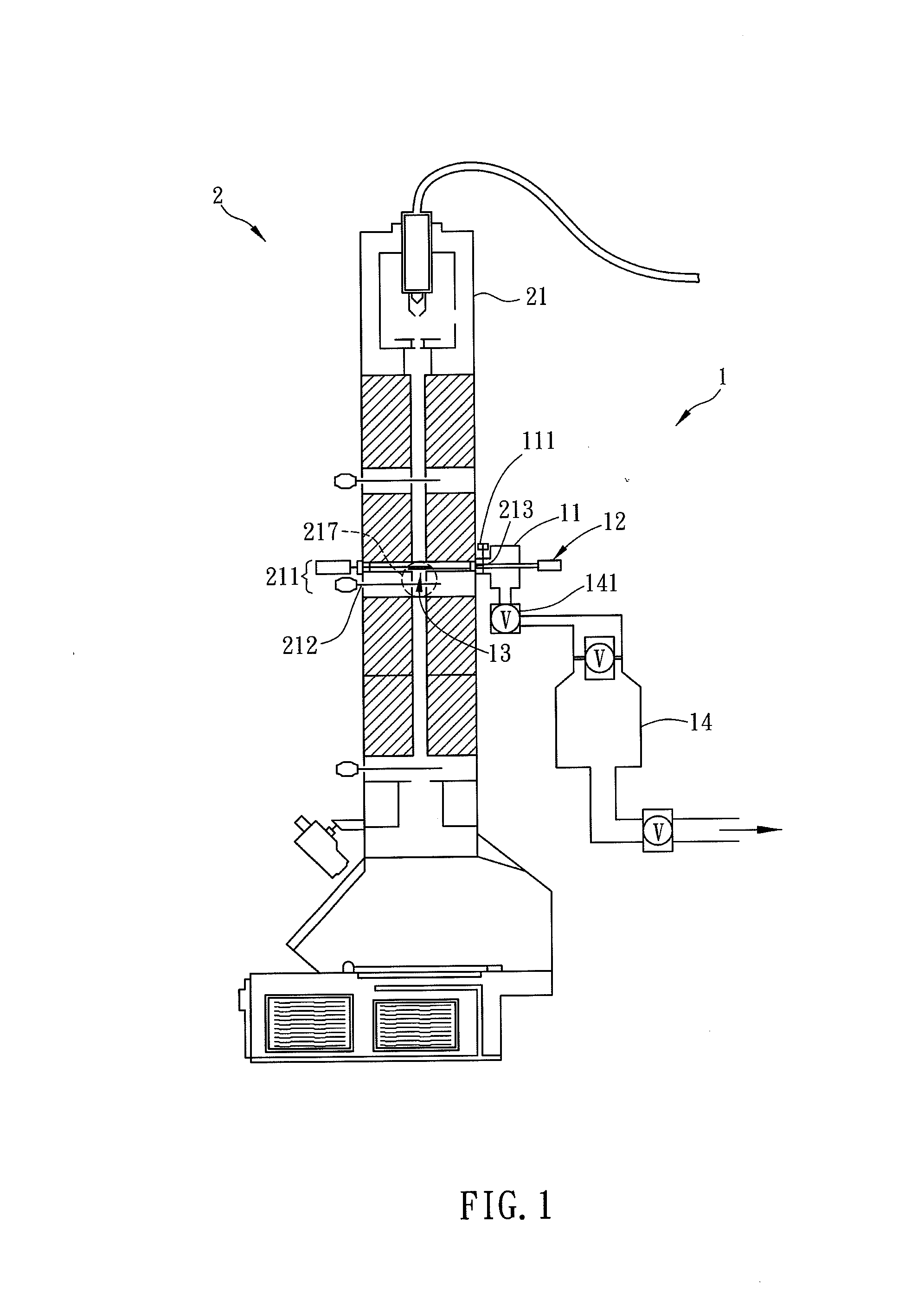
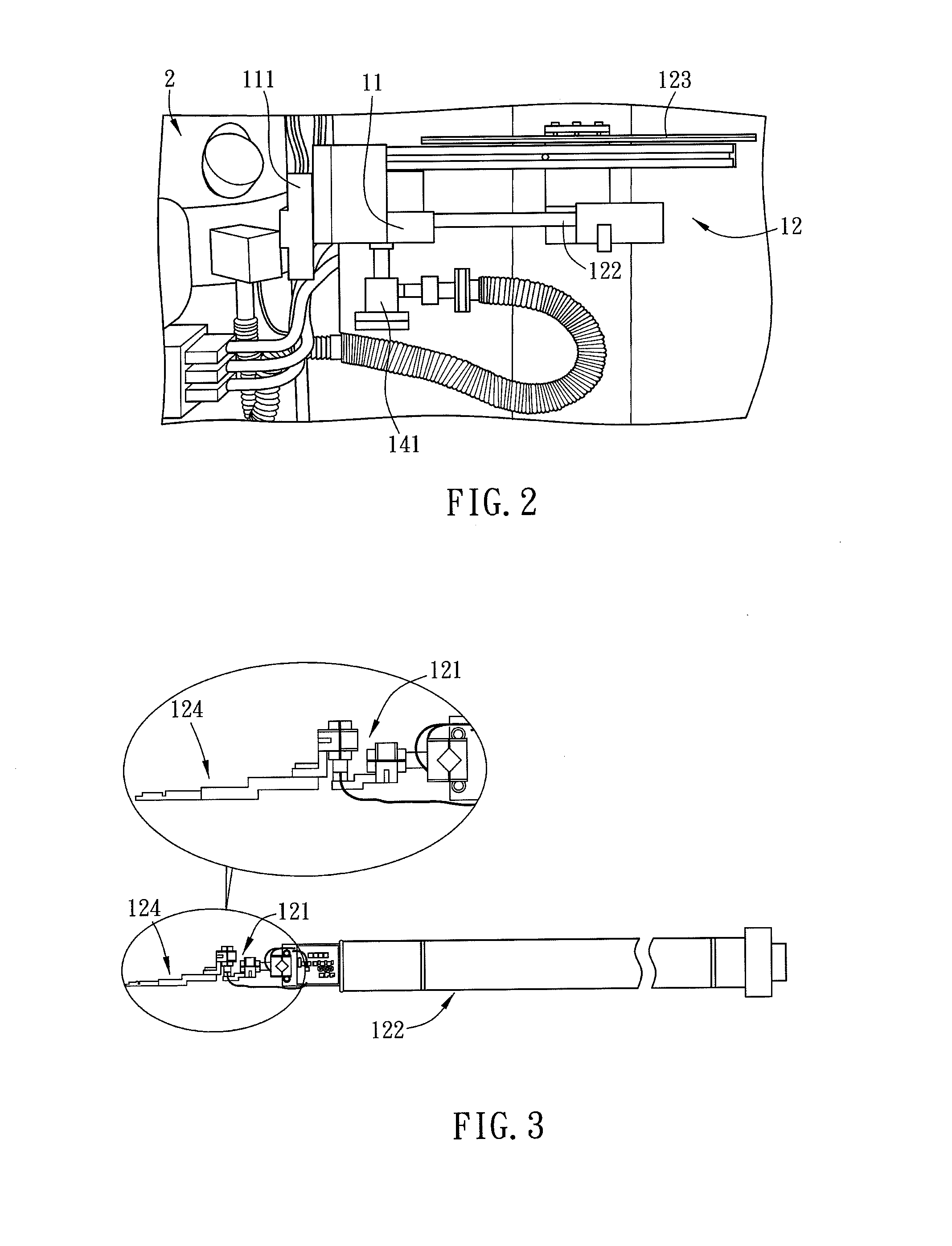
[0028]FIG. 1 is a schematic diagram showing a TEM equipped with a phase plate loading system 1 of the present invention. With reference to FIG. 1, the phase plate loading system 1 applied to a TEM 2 includes an airlock chamber 11 and a transport unit 12.

[0029]As shown in FIG. 1, the TEM 2 is a transmission electron microscope, which is composed of a column portion 21, a vacuum system (not shown) and a control system (not shown). The column portion 21 includes an electron gun section, several lenses sections, a specimen loading section, a fluorescent screen section, a camera, etc. These components are usually installed from top to bottom so as to form a cylindrical configuration. The vacuum system is composed of various pumps and several vacuum gate valves, and is connected to the colu...


PUM


Abstract

A phase plate loading system, which can be installed on any commercial TEM (transmission electron microscope) without modifying its optical or lens design, includes an airlock chamber and a transport unit. The airlock chamber is disposed adjacent to the specimen section of the TEM. The transport unit transfers a phase plate into the TEM through the airlock chamber.

Description

CROSS REFERENCE TO RELATED APPLICATIONS[0001]This Non-provisional application claims the benefit of the filing date of provisional application No. 61 / 374,077 filed Aug. 16, 2010, under 35 USC & 119 (e) (1).BACKGROUND OF THE INVENTION[0002]1. Field of Invention[0003]The present invention relates to a phase plate loading system of a transmission electron microscope (TEM).[0004]2. Related Art[0005]The success of a phase TEM adopting a phase plate device is considered to have a high potential to make some impact in various fields, including biology and materials sciences. With a proper phase TEM and the appropriate wave reconstruction method, it is possible to reveal bio-structure information, which can never be obtained by the conventional TEM. In order to develop a phase TEM that is applicable for imaging, tremendous technical difficulties have to be overcome: (1) loading the phase plate into a TEM must not degrade the functions of the TEM; (2) the phase plate needs to be positioned a...

Claims


Application Information

Patent Timeline
IPC IPC(8): H01J37/20H01J37/18
CPCH01J37/147H01J37/18H01J37/20H01J2237/2614
Inventor SHIUE, YUNN-SHINHUNG, SHAO-KANGCHEN, I-HUICHANG, CHIA-SENG
Owner ACAD SINIC
Why Eureka
Try Eureka