LED tube system

a technology of led tubes and led tubes, which is applied in the direction of cathode-ray/electron beam tube circuit elements, lighting and heating apparatus, electrical apparatus, etc., can solve the problems of not being able to connect a fluorescent tube directly to the lighting mains, the operation life of fluorescent lamps is relatively short, and the fluorescent lamps are no longer the most energy-efficient lighting techniques

Inactive Publication Date: 2012-02-23
LEDNED HLDG
View PDF12 Cites 95 Cited by
  • Summary
  • Abstract
  • Description
  • Claims
  • Application Information

AI Technical Summary

Benefits of technology

[0042]In an embodiment of the LED tube system in accordance with the invention at a respective end of the LED tube housing the respective pair of mains input terminals is covered with a cover, wherein the cover comprises two terminal holes corresponding with locations of the mains terminals, wherein the cover can be pushed back and forth along the end of the LED tube housing, wherein the LED tube system is further arranged such that, before mounting, the cover is spaced apart from the end the LED tube system by means of springs to prevent direct contact the terminals, and such that, during mounting, the cover is pushed inward for releasing the mains terminals. This embodiment of the LED tube system has a first variant of a safety device in accordance with the invention. It protects the user against electric shock when mounting the LED tube system in a lighting fixture.
[0043]In an embodiment of the LED tube system in accordance with the invention at a respective end of the LED tube housing an interruption switch is provided in a current path from the mains input terminals to the remaining part of the LED tube system, and which is controlled by an interruption button, wherein the interruption button is placed such that it is pushed inward when the LED tube system is placed in a lighting fixture for closing the interruption switch for establishing the current path. This embodiment of the LED tube system has a second variant of a safety device in accordance with the invention. It protects the user against electric shock when mounting the LED tube system in a lighting fixture.

Problems solved by technology

Despite all this, since the introduction of the LED lamps, the fluorescent lamps are no longer the most energy efficient lighting technique.
Moreover, the operational lifetime of the fluorescent lamps is relatively short, i.e. about 5000 operation hours, which implies regular replacement.
It is not possible to connect a fluorescent tube directly to the lighting mains.
The development of LED towards full-fledged light source has not yet been possible due to technological barriers, such as the incompatibility with existing lighting installations / armatures.
They do not seem to realize that LED lighting can be a sustainable alternative for existing light sources in this market as well.
There is a major reluctance to step over to a new lighting technology due to large investments which have been done in armatures and installations, despite possible economic and ecologic advantages.
The current compatibility problems with the retrofit-range are caused by the following aspects:there is limited physical space for components, i.e. new lighting products need to be implemented in existing systems and therefore need to have the same dimensions as the current lighting products;the shape of the new products must resemble the shape of the old products.
This aspect puts severe design constraints in LED lighting products.
LED's produce a significant amount of heat.
Active cooling systems, which have been reported in the prior art, are not desired in lighting applications because of several disadvantages which it has as well (more components which may get broken, i.e. reduced operational lifetime, noise, not enough space, etc).
A problem with the known LED tube is that they are not fully retrofit.
The known LED tube is not suitable for being used in lighting fixtures having a plurality of LED tubes in series, and in particular two LED tubes.

Method used


Image

  • LED tube system
  • LED tube system
  • LED tube system

Examples


first embodiment

[0166]The first embodiment on the left is a LED tube having a length of 602.9 mm and a diameter of 30.8 mm. This embodiment comprises six high power LED's equal spaced apart (for best light distribution) at a distance of 75.0 mm. A current classification of LED's which is used in the lighting market is as follows:

[0167]low power LED's, driving current below 50 mA;

[0168]mid power LED's, driving current between 50 mA and 150 mA;

[0169]high power LED's, driving current above 350 mA (they can be driven at lower currents, but then their efficiency is generally lower).

[0170]The power consumption of the first embodiment is 10.5 Watt and the power factor lies in the range 0.83-0.92. The second embodiment from the left is a LED tube having a length of 983.3 mm and a diameter of 30.8 mm. This embodiment comprises ten high power LED's equal spaced apart (for best light distribution) at a distance of 85.0 mm. The power consumption is 17 Watt and the power factor lies in the range 0.84-0.91. The ...

second embodiment

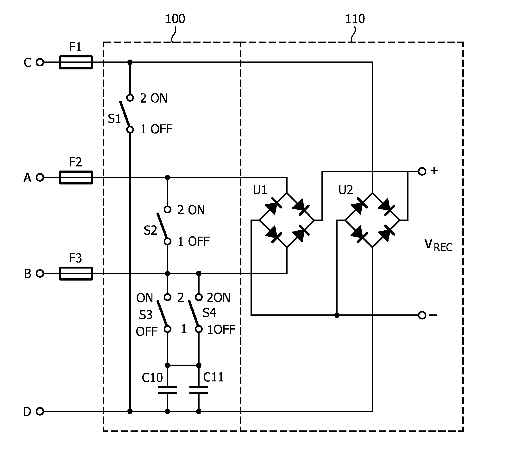
[0172]FIG. 11 shows an equivalent circuit diagram of the LED system in accordance with the second embodiment in FIG. 9. The major difference with FIG. 10 is that this LED tube system comprises a third driver circuit 170 which drives a second series connection of LED's 210. In this embodiment the first series connection 200 comprises seven LED's and the second series connection 210 comprises three LED's. Another difference is that the coupling capacitors C10, C11 in the switching circuit 110 are both 2.2 μf, which brings the total capacitance value to 4.4 μf. This value complies with the AC power of 14.5 Watt in this embodiment.

third embodiment

[0173]FIG. 12 shows an equivalent circuit diagram of the LED system in accordance with the third embodiment in FIG. 9. The major difference with FIG. 10 is that this LED tube system comprises a fourth driver circuit 180 which drives the second series connection of LED's 210. In this embodiment the first series connection 200 comprises six LED's and the second series connection 210 comprises six LED's. Another difference is that the there are now three coupling capacitors C10, C11, C12 in the switching circuit 110 of 2.2 μf, 2.2 μf, and 0.33 μf, respectively, which brings the total capacitance value to 4.73 μf. This value complies with the AC power of 17 Watt in this embodiment.


PUM


Abstract

The invention relates to an LED tube system for driving at least one LED assembly comprising: an LED tube housing for containing the at least one LED assembly, two pairs of mains input terminals (A, B) provided at ends of the LED tube housing for receiving a mains supply voltage (Vmns) and for supplying the mains supply voltage (Vmns) to an internal part of the LED tube system for driving the at least one LED assembly, and further comprising a switching circuit being electrically connected with all mains input terminals (A, B, C, D) and being arranged for electrically connecting the pairs of mains input terminals together in a first state (2/ON) and electrically separating the pairs in a second state (1/OFF) of the switching circuit. The switching circuit being further arranged for providing a coupling capacitor (C10, C11) between the first pair and the second pair of input terminals in the first state (2/ON) and removing the coupling capacitor (C10, C11) in the second state (1/OFF) of the switching circuit. Due to the switching circuit the LED tube system in accordance with the invention can be used in lighting fixtures for parallel fluorescent tubes as well as in lighting fixtures for serial fluorescent tubes. The invention further relates to safety devices for the LED tube system.

Description

FIELD OF THE INVENTION[0001]The invention relates to a LED tube system for driving at least one LED assembly. The invention further relates to safety devices for such LED tube system.BACKGROUND OF THE INVENTION[0002]Most lighting products in both the professional and private market consist of fluorescent lamps. Mostly, these fluorescent lamps are fluorescent tubes. A fluorescent lamp utilizes a fluorescent substance which converts ultraviolet radiation in the lamp into visible light. The efficiency of the fluorescent lamps is higher than that of the incandescent lamps, i.e. 90 Lumen / Watt versus 12 Lumen / Watt. Despite all this, since the introduction of the LED lamps, the fluorescent lamps are no longer the most energy efficient lighting technique. Moreover, the operational lifetime of the fluorescent lamps is relatively short, i.e. about 5000 operation hours, which implies regular replacement.[0003]Every year 12.5 million fluorescent lamps are released on the Dutch market. In practi...

Claims


Application Information

Patent Timeline
Patent Type & Authority Applications(United States)
IPC IPC(8): H05B37/02H05B44/00
CPCF21V25/04F21Y2101/02H01R13/4538H01R33/942F21Y2103/003H05B33/0809Y02B20/386F21K9/175H05B33/0803F21Y2103/10F21Y2115/10F21K9/272Y02B20/30H05B45/355H05B45/385H05B45/3578
Inventor VISSER, JURJEN HILWERTYU, GUANG ZHIZENG, SHUANG HESTAUDT, MICHAEL FRIEDRICH ALBERTSHEA, SHU KEISTAUDT, CARL RUDOLF EDUARD
Owner LEDNED HLDG
Why Eureka
Try Eureka