
Backlight module and a LCD thereof

Inactive Publication Date: 2012-02-23
TCL CHINA STAR OPTOELECTRONICS TECH CO LTD
View PDF8 Cites 9 Cited by
  • Summary
  • Abstract
  • Description
  • Claims
  • Application Information

AI Technical Summary

Benefits of technology

[0007]It is therefore an object of the present invention to provide a backlight module and an LCD employing such a module by means of an alternate driving lighting device to reduce thermal power generation.
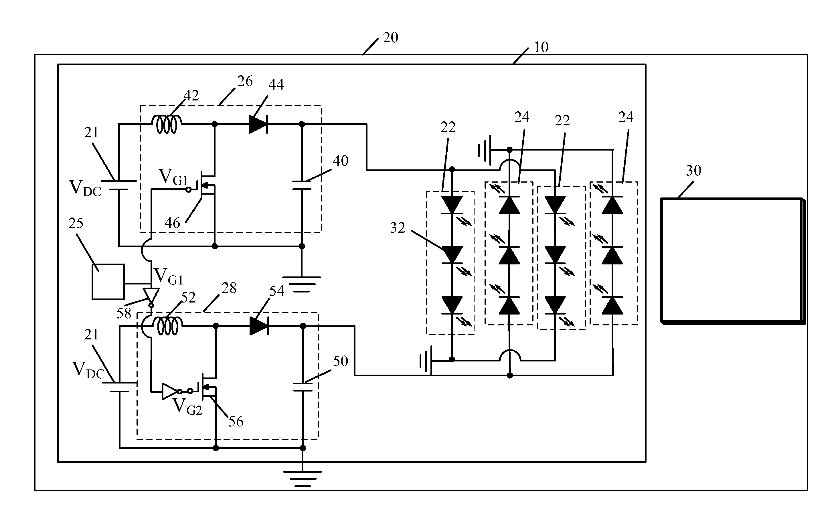
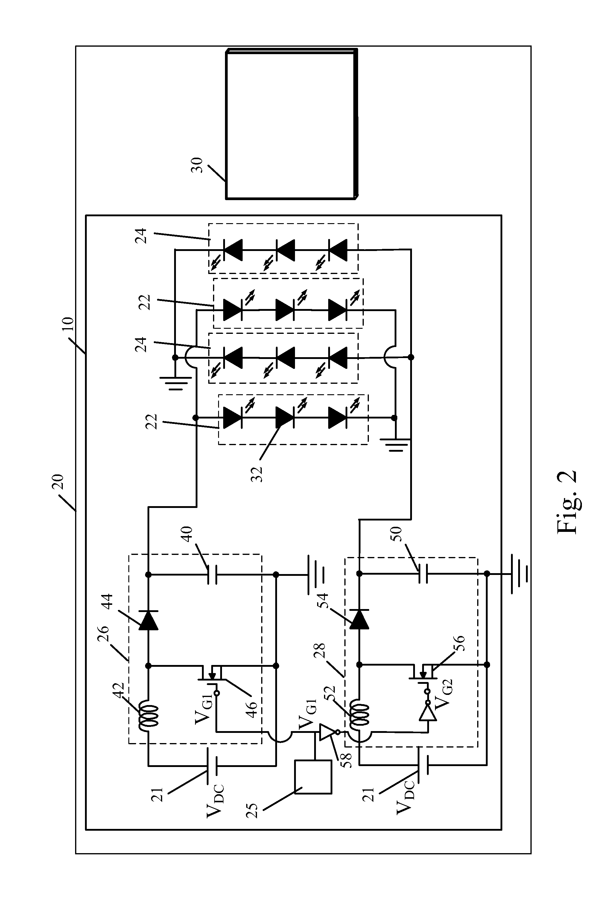
[0015]Compared with the prior art, the backlight module with the related LCD in the present invention activates LEDs by using an alternate control method. If a duty cycle is set at 50 percent during a switching cycle period, the LEDs in the same string will be in a closed state in a duty cycle of 50 percent. And, all of the switching frequencies are above 1 kHz, so human eyes cannot detect variations in brightness of the LEDs. Besides, excess temperature produced by the LEDs when lightened simultaneously and thermal power generated during the lighting of the LEDs can be effectively reduced for the reason that the LEDs are in a closed condition in half or even more of the time during the switching cycle period.

Problems solved by technology

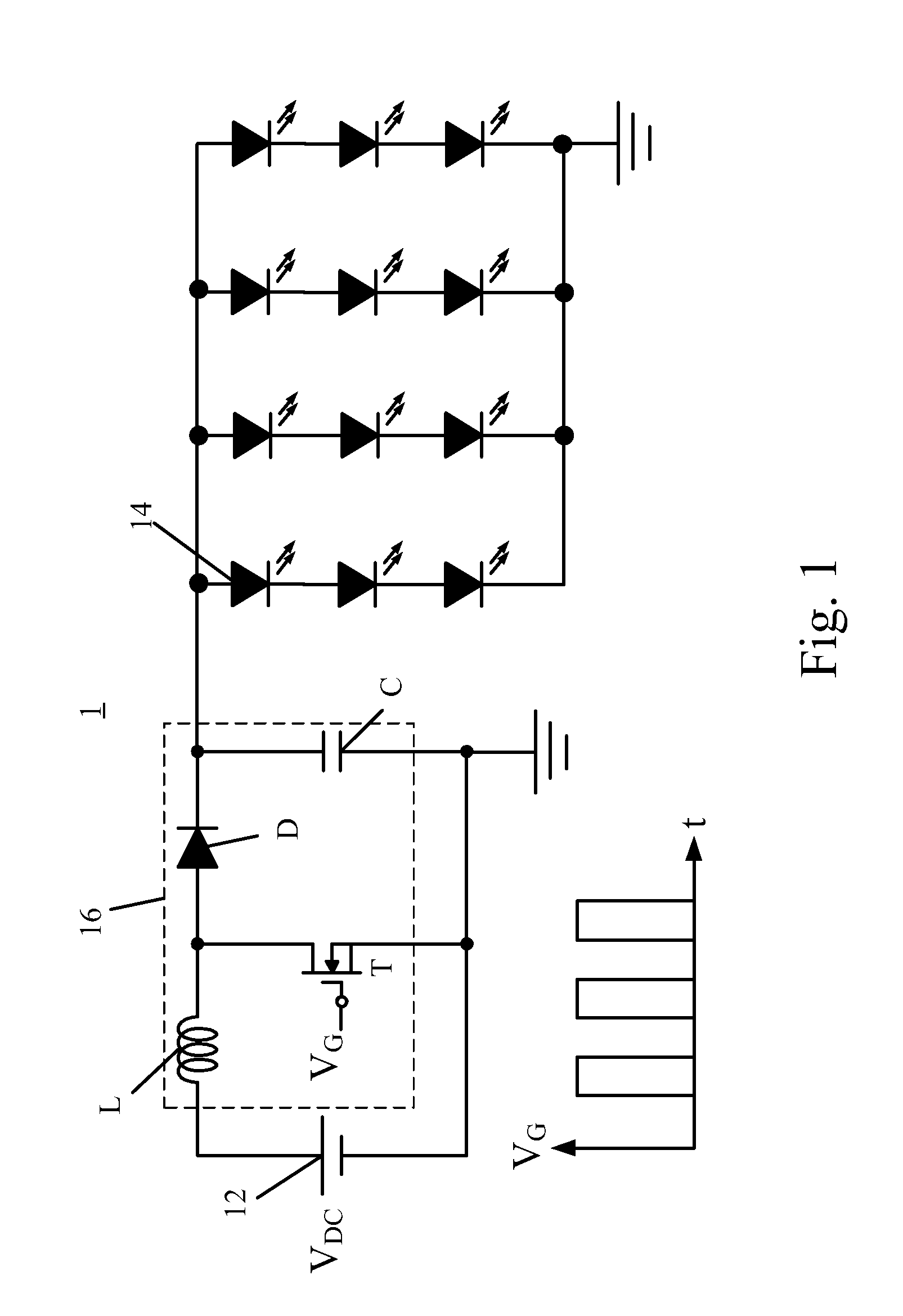
But, large currents may also cause some potential problems, such as excess temperature, which not only shortens the lifespan of the LEDs 14 but also reduce the luminous efficiency of the LEDs 14.

Method used


Image

  • Backlight module and a LCD thereof
  • Backlight module and a LCD thereof
  • Backlight module and a LCD thereof

Examples


Embodiment Construction

[0020]Referring to FIG. 2, FIG. 2 is a schematic diagram of a liquid crystal display (LCD) 20 according to a first embodiment of the present invention. The LCD 20 comprises a power end 21, an LCD panel 30, and a backlight module 10. The backlight module 10 produces light that the LCD panel 30 requires with a voltage provided by the power end 21. The backlight module 10 comprises a first lighting device 22, a second lighting device 24, a switch signal generator 25, a first inverter 26, and a second inverter 28. The power end 21 provides a DC supply voltage VDC. The LCD panel 30 comprises a liquid crystal (LC) layer for displaying images. The first lighting device 22 and the second lighting device 24 comprise a single LED 32 or a plurality of LEDs 32 in serial. The first lighting device 22 comprises one end electrically connected to the first inverter 26 and the other end electrically connected to a voltage end (a ground end in FIG. 2) for producing light based on the voltage differen...


PUM


Abstract

The present invention discloses a backlight module with a related liquid crystal display (LCD) which activates light emitting diodes (LEDs) by utilizing an alternate control method. The present invention utilizes two inverters to individually activate two sets of LEDs through an alternate method. During the same switching cycle period, the two sets of LEDs take turns turning on / off; that is, the two set of LEDs are in a closed state in a duty cycle of 50 percent. Since each set of the LEDs are in a closed condition in half the time during a switching cycle period, both of excess temperature produced by all of the LEDs when lightened simultaneously and thermal power generated during the lighting of the LEDs can be effectively reduced.

Description

BACKGROUND OF THE INVENTION[0001]1. Field of the Invention[0002]The present invention relates to a backlight module and a liquid crystal display (LCD) employing such a backlight module, and more particularly, to a backlight module for alternately driving lighting device and an LCD employing such a backlight module.[0003]2. Description of Prior Art[0004]With a rapid development of monitor types, novel and colorful monitors with high resolution, e.g., liquid crystal displays (LCDs), are indispensable components used in various electronic products such as monitors for notebook computers, personal digital assistants (PDAs), digital cameras, and projectors. The demand for the novelty and colorful monitors has increased tremendously.[0005]A backlight module is a key component of a liquid crystal display (LCD). The purpose of the backlight module is to provide a sufficient-brightness and an even-distribution light surface to the LCD panel. Because the LCD is widely used in various electron...

Claims


Application Information

Patent Timeline
IPC IPC(8): G09G3/36G09G5/10H05B41/16H05B44/00
CPCH05B33/0815H05B33/0845Y02B20/346G09G2330/025G09G3/3406G02F1/133603H05B45/38Y02B20/30H05B45/3725G02F1/133612G02F1/133613G02F1/133628
Inventor HE, CHENGMINGYANG, CHINGYUAN
Owner TCL CHINA STAR OPTOELECTRONICS TECH CO LTD
Learn More