Illuminating device with light emitting diodes

a technology of light-emitting diodes and illumination devices, which is applied in semiconductor devices, lighting and heating apparatus, and light-emitting support devices. it can solve the problems of deterioration and illumination decay of light-emitting diodes, inability of light-emitting diodes to efficiently disperse the thermal energy generated by light-emitting diodes, and high working temperature of light-emitting diodes. , to achieve the effect of improving th

Inactive Publication Date: 2012-02-23
LM OPTO
View PDF1 Cites 17 Cited by
  • Summary
  • Abstract
  • Description
  • Claims
  • Application Information

AI Technical Summary

Benefits of technology

[0020]The illuminating device with light emitting diodes of the present invention increases an area in contact with the light emitting diodes to highly reduce working temperature of the light emitting diodes, thereby decreasing

Problems solved by technology

However, light emitting diode modules would also generate thermal energy when lightening, so that generated thermal energy would be constantly accumulated for a long illuminating time.
Finally, light emitting diode modules would have some problems about deterioration and illumination decay due to the accumulated thermal energy.
However, the light emitting diode housing cannot dissipate the thermal energy generated from the light emitting diode module efficiently.
Ther

Method used


Image

  • Illuminating device with light emitting diodes
  • Illuminating device with light emitting diodes
  • Illuminating device with light emitting diodes

Examples


Embodiment Construction

[0026]In the following detailed description, for purposes of explanation, numerous specific details are set forth in order to provide a thorough understanding of the disclosed embodiments. It will be apparent, however, that one or more embodiments may be practiced without these specific details. In other instances, well-known structures and devices are schematically shown in order to simplify the drawings.

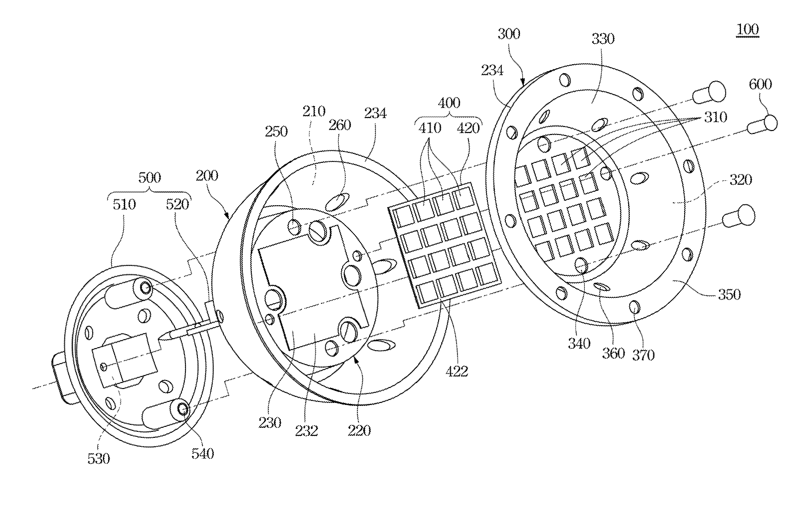
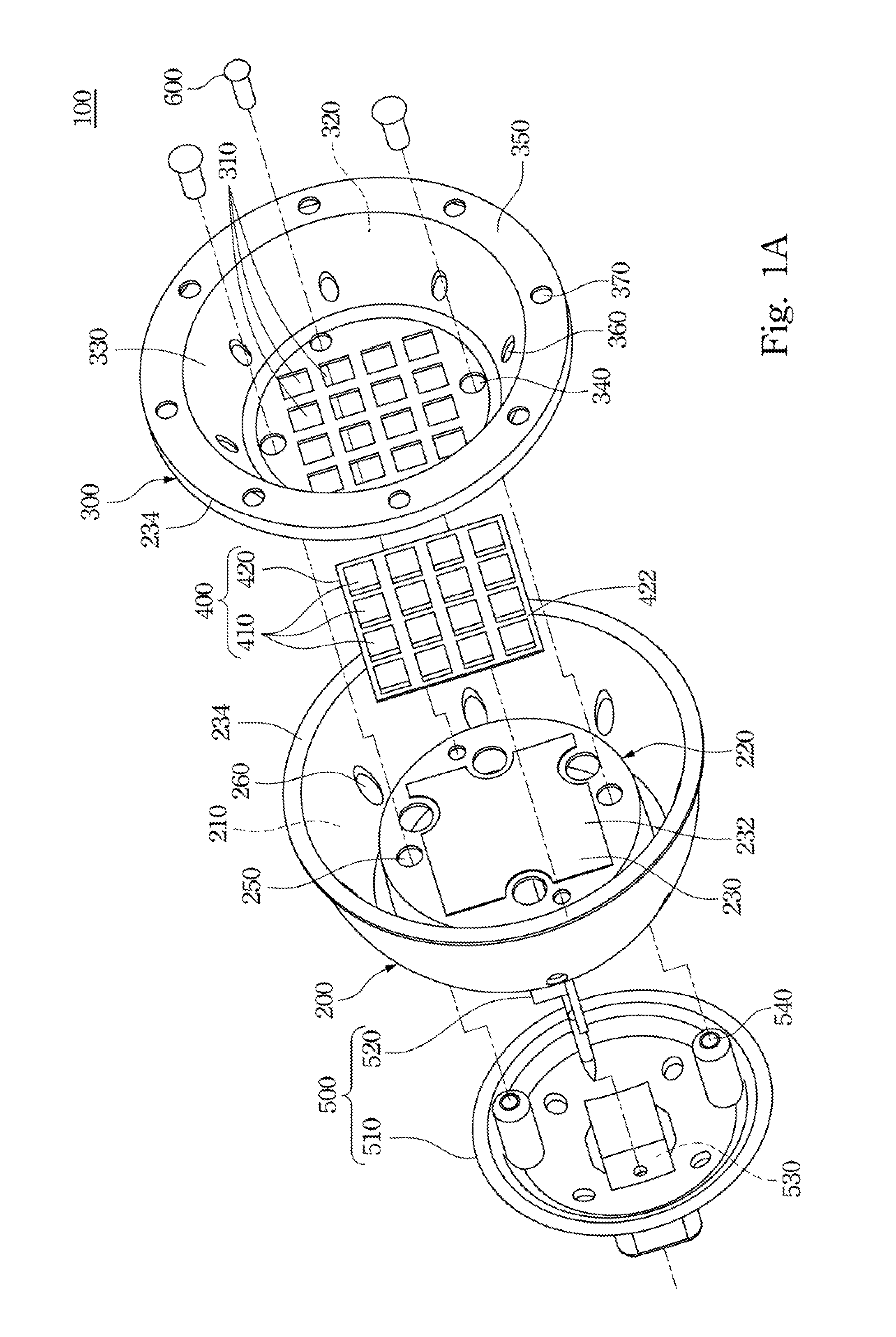
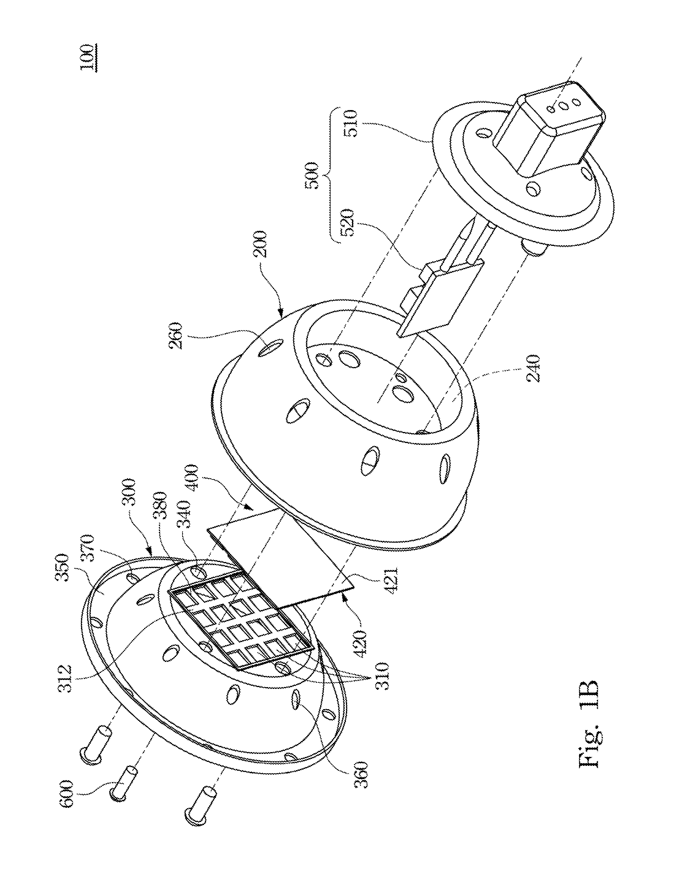
[0027]An illuminating device with light emitting diodes is provided in the present disclosure. The illuminating device includes a rear housing, a front housing, and an illuminating module. The front housing includes through holes. The illuminating module is sandwiched between the rear housing and the front housing. The illuminating device includes light emitting diodes extending through the through holes in a one-to-one relationship.

[0028]As such, due to the illuminating module sandwiched between the front housing and the rear housing, the thermal energy generated from the working ...


PUM


Abstract

An illustrator with light emitting diodes provided in the invention includes a rear housing having a cavity. A front housing is disposed in the cavity, wherein the front housing includes through holes. An illuminating module is sandwiched between the rear housing and the front housing, wherein the illuminating module includes a substrate and light emitting diodes. Two opposite surfaces of the substrate are in contact with the rear housing and the front housing respectively and directly. The light emitting diodes are arranged on a surface of the substrate in an array arrangement and extending outward the through holes in a one-to-one relationship.

Description

RELATED APPLICATIONS[0001]This application claims priority to Taiwan Application Serial Number 099127765, filed Aug. 19, 2010, which is herein incorporated by reference.BACKGROUND[0002]1. Technical Field[0003]The present disclosure relates to an illuminating device, more particularly to an illuminating device with light emitting diodes.[0004]2. Description of Related Art[0005]In daily life, illuminating apparatuses are necessarily important tools for people. Light bulbs or lamps of illuminating apparatuses are used as main light sources nowadays. Because these Light bulbs or lamps would consume more electric power when working, such as fluorescent lamps, incandescent bulbs, halogen lamps, or halogen bulbs, light sources mentioned above are replaced with modules made of light emitting diodes gradually in the present day for energy saving and carbon reduction.[0006]However, light emitting diode modules would also generate thermal energy when lightening, so that generated thermal energ...

Claims


Application Information

Patent Timeline
IPC IPC(8): F21V7/00F21S4/00
CPCF21K9/1375F21V19/0035F21V19/0055F21Y2101/02F21V29/89F21V29/505F21V29/507F21V29/83F21V29/85F21Y2105/001F21K9/23F21Y2105/10F21Y2115/10
Inventor LIN, PAO-TINGTSENG, YU-CHU
Owner LM OPTO
Why Eureka
Try Eureka