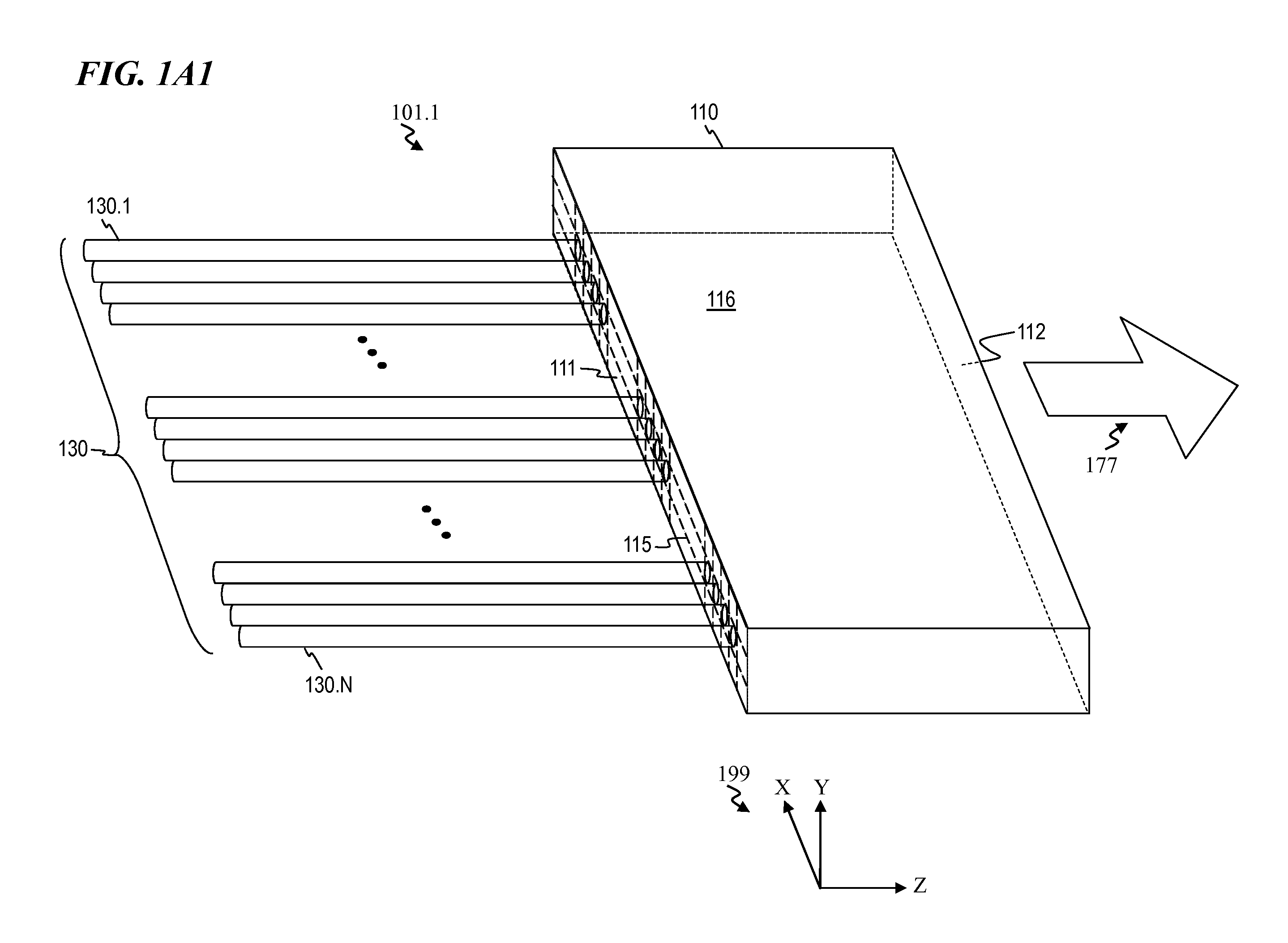
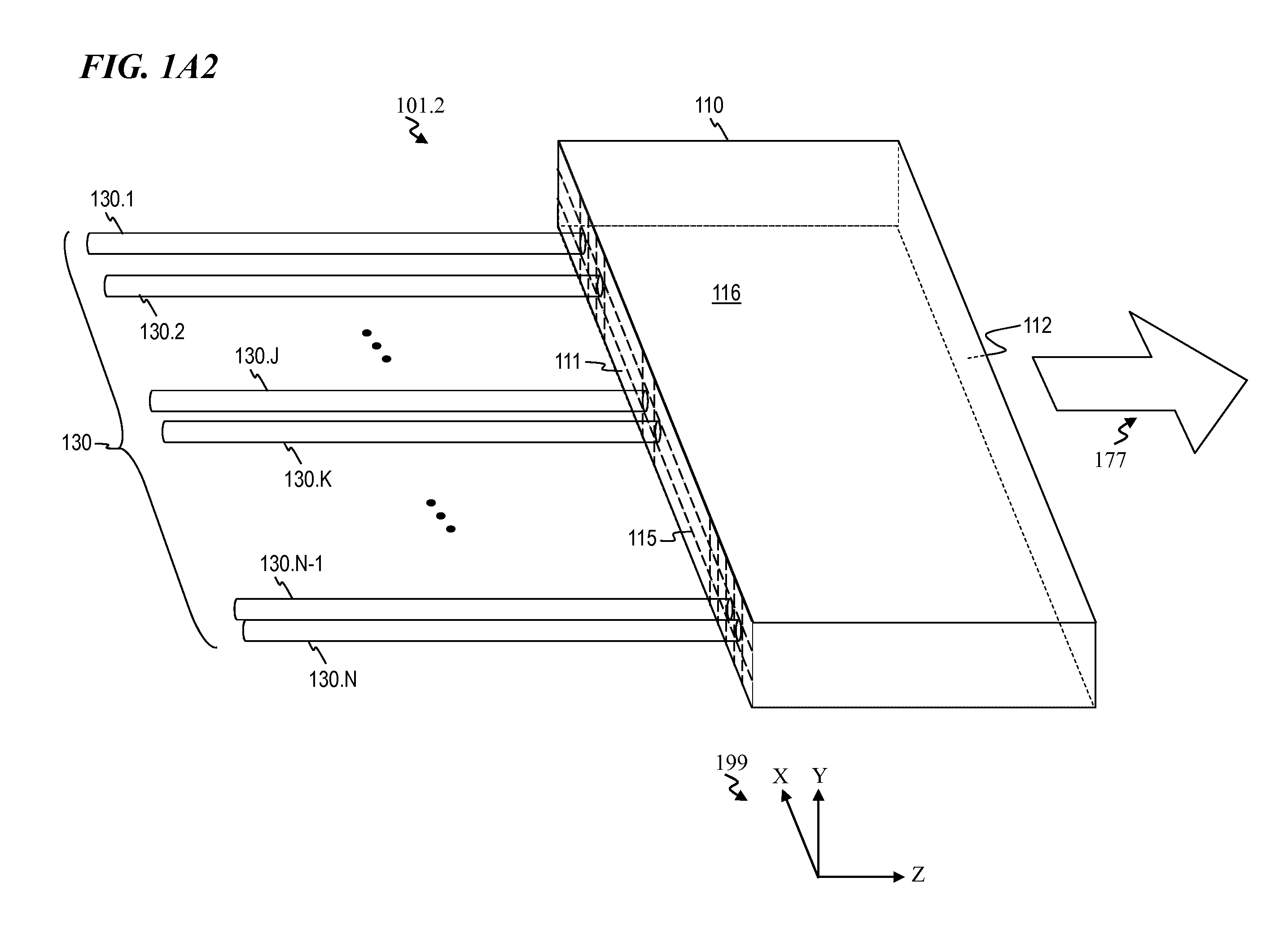
Optical-fiber array method and apparatus

a technology of optical fiber arrays and arrays, applied in the field of optical waveguides, can solve the problems of limited power handling capability of conventional fiber array systems, excessive optical aberration and limited manufacturing of existing optical fiber arrays

Inactive Publication Date: 2012-02-23
LOCKHEED MARTIN CORP
View PDF31 Cites 61 Cited by
  • Summary
  • Abstract
  • Description
  • Claims
  • Application Information

AI Technical Summary

Problems solved by technology

Existing optical-fiber arrays are generally difficult to manufacture because of the required alignment precision between fibers.
Many conventional fiber-array systems, like V-groove-based substrates that hold an array of fibers, also have limited power-handling capability.
In addition, for applications such as spectral-beam combining, existing optical-fiber arrays present excessive optical aberrations from their extended source of light.

Method used


Image

  • Optical-fiber array method and apparatus
  • Optical-fiber array method and apparatus
  • Optical-fiber array method and apparatus

Examples


Embodiment Construction

[0068]Although the following detailed description contains many specifics for the purpose of illustration, a person of ordinary skill in the art will appreciate that many variations and alterations to the following details are within the scope of the invention. Accordingly, the following preferred embodiments of the invention are set forth without any loss of generality to, and without imposing limitations upon the claimed invention.

[0069]In the following detailed description of the preferred embodiments, reference is made to the accompanying drawings that form a part hereof, and in which are shown by way of illustration specific embodiments in which the invention may be practiced. It is understood that other embodiments may be utilized and structural changes may be made without departing from the scope of the present invention.

[0070]The leading digit(s) of reference numbers appearing in the Figures generally corresponds to the Figure number in which that component is first introduc...


PUM

PropertyMeasurementUnit
peak-power-handling capabilityaaaaaaaaaa
peak poweraaaaaaaaaa

Abstract

Method and apparatus for forming an optical-fiber-array assembly, which include providing a plurality of optical fibers including a first optical fiber and a second optical fiber, providing a fiber-array plate that includes a first surface and a second surface, connecting the plurality of optical fibers to the first surface of the fiber-array plate, transmitting a plurality of optical signals through the optical fibers into the fiber-array plate at the first surface of the fiber-array plate, and emitting from the second surface of the fiber-array plate a composite output beam having light from the plurality of optical signals. Optionally, the first surface of the fiber-array plate includes indicia configured to assist in the alignment of the plurality of optical fibers on the first surface of the fiber-array plate. In some embodiments, the second surface of the fiber-array plate includes a plurality of beam-shaping optics configured to shape the composite output beam.

Description

CROSS-REFERENCE TO RELATED APPLICATIONS[0001]This invention is related to:[0002]U.S. Pat. No. 7,539,231 titled “APPARATUS AND METHOD FOR GENERATING CONTROLLED-LINEWIDTH LASER-SEED-SIGNALS FOR HIGH-POWERED FIBER-LASER AMPLIFIER SYSTEMS” that issued May 26, 2009 to Eric C. Honea et al. (Attorney Docket 5032.004US1),[0003]U.S. Pat. No. 7,471,705 titled “ULTRAVIOLET LASER SYSTEM AND METHOD HAVING WAVELENGTH IN THE 200-NM RANGE” that issued Dec. 30, 2008 to David C. Gerstenberger et al. (Attorney Docket 5032.005US1),[0004]U.S. Pat. No. 7,391,561 titled “FIBER- OR ROD-BASED OPTICAL SOURCE FEATURING A LARGE-CORE, RARE-EARTH-DOPED PHOTONIC-CRYSTAL DEVICE FOR GENERATION OF HIGH-POWER PULSED RADIATION AND METHOD” that issued Jun. 24, 2008 to Fabio Di Teodoro et al. (Attorney Docket 5032.008US1),[0005]U.S. Pat. No. 7,671,337 titled “SYSTEM AND METHOD FOR POINTING A LASER BEAM” that issued Mar. 2, 2010 to Steven C. Tidwell (Attorney Docket 5032.012US1),[0006]U.S. Pat. No. 7,199,924 titled “APPA...

Claims


Application Information

Patent Timeline
Patent Type & Authority Applications(United States)
IPC IPC(8): G02B6/32B23P19/04B23K11/02G02B6/04
CPCB23K1/0008Y10T29/49826B23K26/26B23K26/3266B23K2201/32B23K2203/08B23K2203/18G02B6/262G02B6/29311G02B6/32G02B6/3652G02B6/3672G02B6/4296G02B6/272G02B6/2726G02B6/2773G02B6/2843B23K1/0056B23K26/32B23K2103/54B23K2101/32B23K2103/18B23K2103/50B23K2103/52
Inventor HU, YONGDANLEMAIRE, CHARLES A.
Owner LOCKHEED MARTIN CORP
Why Eureka
Try Eureka