
Fuel cell module

a fuel cell and module technology, applied in the direction of fuel cells, fuel cells, cell components, etc., can solve the problems of easy damage to the fuel cell at the lowermost position of the fuel cell stack, and achieve the effects of reducing the consumption of fuel gas, preventing damage to the electrolyte electrode assembly, and efficient supply of fuel gas

Active Publication Date: 2012-02-23
HONDA MOTOR CO LTD
View PDF1 Cites 0 Cited by
  • Summary
  • Abstract
  • Description
  • Claims
  • Application Information

AI Technical Summary

Benefits of technology

[0008]The present invention has been made to solve the problem of this type, and an object of the present invention is to provide a fuel cell module having simple and economical structure in which it is possible to reliably prevent damages or the like of MEAs due to the own weight of the MEAs positioned at ends, reduce the amount of wastefully discharged fuel gas as much as possible, and achieve improvement in the efficiency.
[0011]According to the present invention, at one end of the fuel cell stack in the stacking direction, the end separator limiting the supply of the fuel gas to the fuel gas channel is provided. Therefore, the fuel gas is not supplied wastefully. In the structure, consumption of the fuel gas is reduced, and the fuel gas can be supplied efficiently.
[0012]Further, since the load absorption member is provided at the other end of the fuel cell stack in the stacking direction, the load in the stacking direction is suitably absorbed, and damages of the electrolyte electrode assembly can be prevented. Further, since the load absorption member is provided instead of the electrolyte electrode assembly, damages of the electrolyte electrode assembly can be prevented without increasing the number of stacked components. Moreover, wasteful consumption of the fuel cell is reduced suitably.

Problems solved by technology

Therefore, the fuel cell at the lowermost position of the fuel cell stack tends to be damaged easily.

Method used


Image

  • Fuel cell module
  • Fuel cell module
  • Fuel cell module

Examples


first embodiment

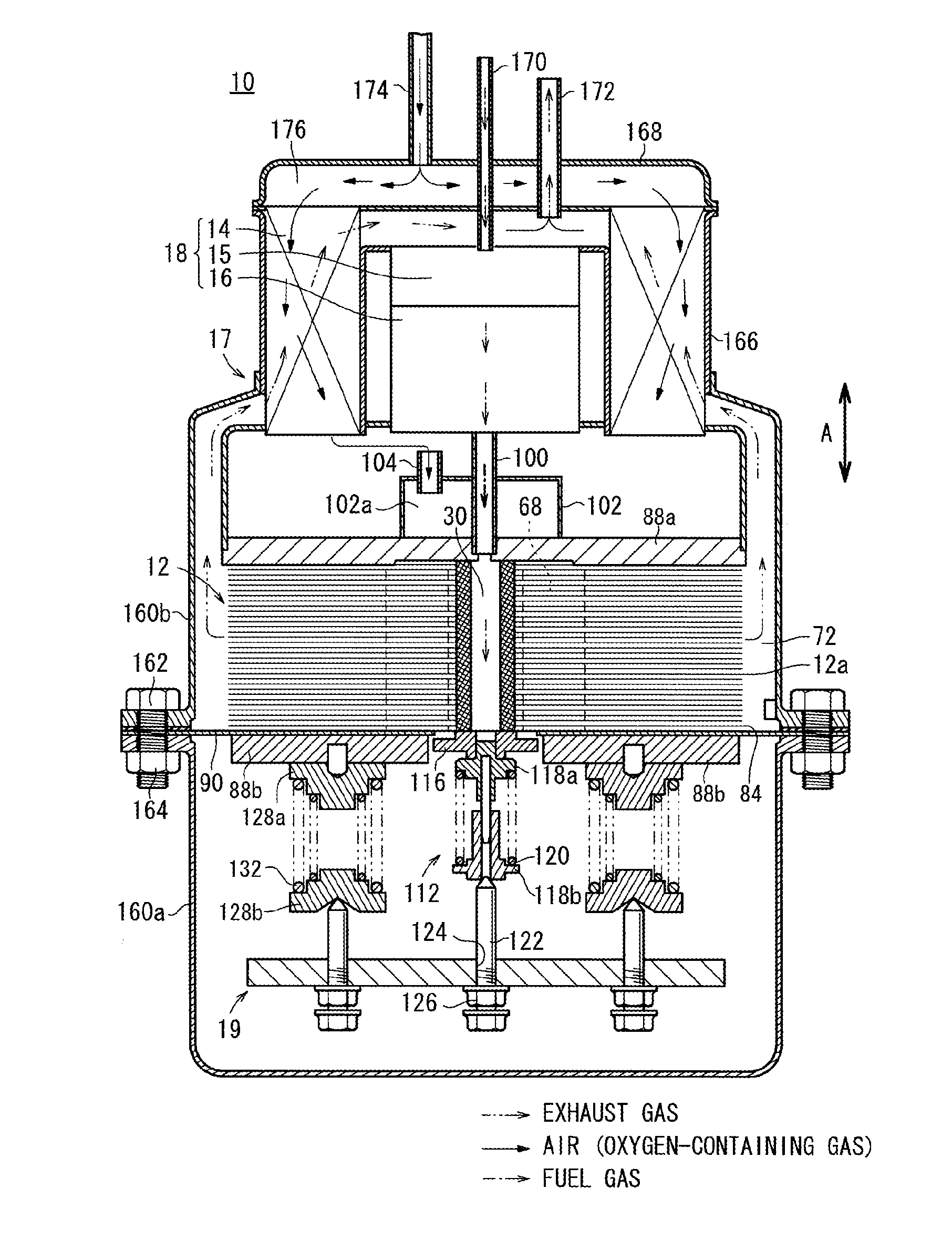
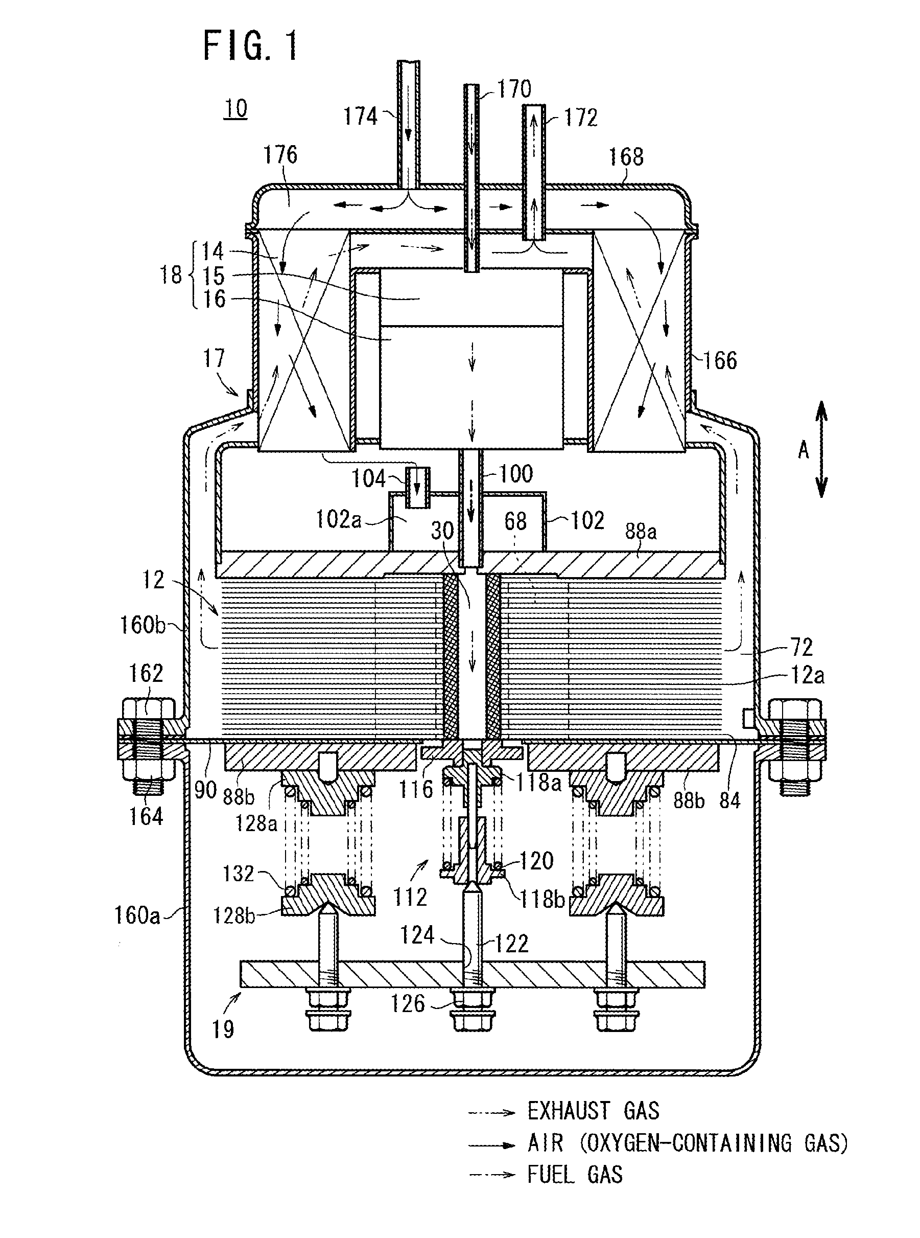
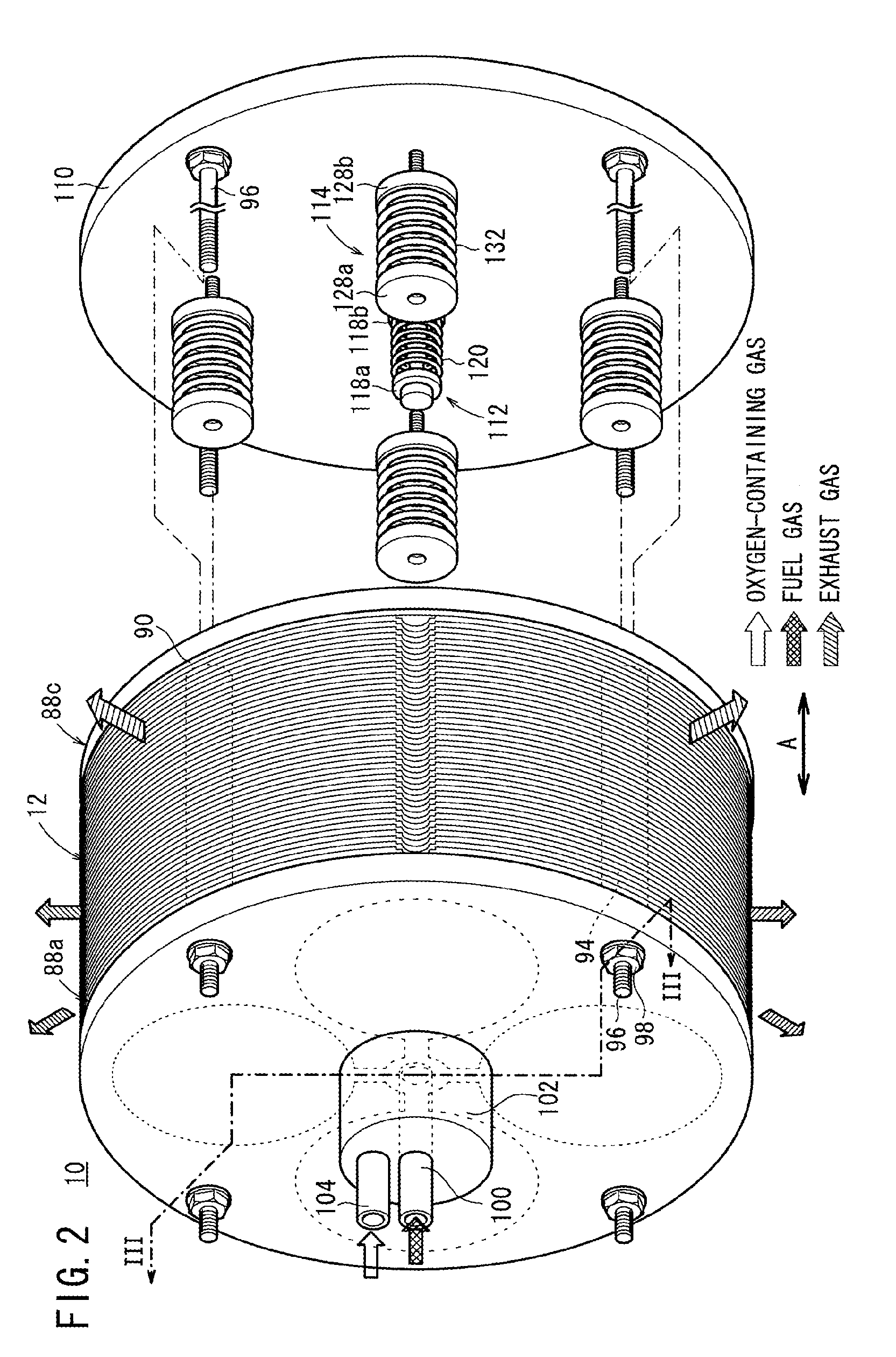
[0026]As shown in FIGS. 1 to 3, a fuel cell module 10 according to the present invention is used in various applications, including stationary and mobile applications. For example, the fuel cell module 10 is mounted on a vehicle.

[0027]The fuel cell module 10 includes a fuel cell stack 12, a heat exchanger 14 for heating the oxygen-containing gas before it is supplied to the fuel cell stack 12, an evaporator 15 for evaporating water to produce a mixed fuel of the raw fuel and the water vapor, a reformer 16 for reforming the mixed fuel to produce a reformed gas, and a casing 17 containing the fuel cell stack 12, the heat exchanger 14, the evaporator 15, the reformer 16, and a load applying mechanism 19 as described later.

[0028]The reformer 16 reforms higher hydrocarbons (C2+) such as ethane (C2H6), propane (C3H8), and butane (C4H10) in the city gas (raw fuel) to produce the fuel gas chiefly containing methane (CH4), hydrogen, and CO by steam reforming as a preliminary reformer, and th...

second embodiment

[0082]FIG. 9 is a cross sectional view showing a load absorption member 180 of a fuel cell module according to the present invention.

[0083]The constituent elements that are identical to those of the load absorption member 86 according to the first embodiment are labeled with the same reference numerals, and descriptions thereof will be omitted. Also in third to fifth embodiments as described later, the constituent elements that are identical to those of the load absorption member 86 according to the first embodiment are labeled with the same reference numerals, and descriptions thereof will be omitted.

[0084]The load absorption member 180 is a metal stack body formed by integrally stacking a pair of flat metal plates 182a, 182b, and a corrugated metal plate 184 sandwiched between the metal plates 182a, 182b together.

[0085]Thus, in the second embodiment, electrical energy generated in the power generation can be transmitted efficiently. In particular, since the corrugated metal plate ...

third embodiment

[0086]FIG. 10 is a cross sectional view showing a load absorption member 190 of a fuel cell module according to the present invention. The load absorption member 190 is made of foamed metal.


PUM

PropertyMeasurementUnit
operating temperatureaaaaaaaaaa
shapeaaaaaaaaaa
electrically conductiveaaaaaaaaaa

Abstract

In a fuel cell stack constituting a fuel cell module, electrolyte / electrode assemblies and separators are alternately laminated. An electrolyte / electrode assembly is arranged on one end of the fuel cell stack in the lamination direction, while a separator is arranged on the other end of the fuel cell stack in the lamination direction. A terminal separator is arranged adjacent to the electrolyte / electrode assembly, while a load relaxation member is arranged adjacent to the separator. The terminal separator controls the supply of a fuel gas to a fuel gas channel, and the load relaxation member is configured of a laminate of a plurality of flat metal plates.

Description

TECHNICAL FIELD[0001]The present invention relates to a fuel cell module including a fuel cell stack formed by stacking electrolyte electrode assemblies and separators alternately. Each of the electrolyte electrode assemblies includes an anode, a cathode, and an electrolyte interposed between the anode and the cathode.BACKGROUND ART[0002]Typically, a solid electrolyte fuel cell (SOFC) employs an electrolyte of ion-conductive oxide such as stabilized zirconia. The electrolyte is interposed between an anode and a cathode to form an electrolyte electrode assembly (MEA). The electrolyte electrode assembly is interposed between separators (bipolar plates). In use, normally, predetermined numbers of the electrolyte electrode assemblies and the separators are stacked together to form a fuel cell stack.[0003]In the fuel cell stack, since the electrolyte electrode assemblies and the separators are stacked alternately in the vertical direction, in particular, the entire weight of the fuel cel...

Claims


Application Information

Patent Timeline
Patent Type & Authority Applications(United States)
IPC IPC(8): H01M8/24H01M8/06
CPCH01M8/12H01M8/247Y02E60/525H01M8/249Y02E60/521H01M8/248H01M8/2432H01M8/2457Y02E60/50
Inventor NANGO, AYAKAOGAWA, TETSUYAKIYOHIRO, YUKIHIKO
Owner HONDA MOTOR CO LTD
Learn More