
Method for determining a toothed rack force for a steering device in a vehicle

Active Publication Date: 2012-02-23
ROBERT BOSCH AUTOMOTIVE STEERING
View PDF26 Cites 14 Cited by
  • Summary
  • Abstract
  • Description
  • Claims
  • Application Information

AI Technical Summary

Benefits of technology

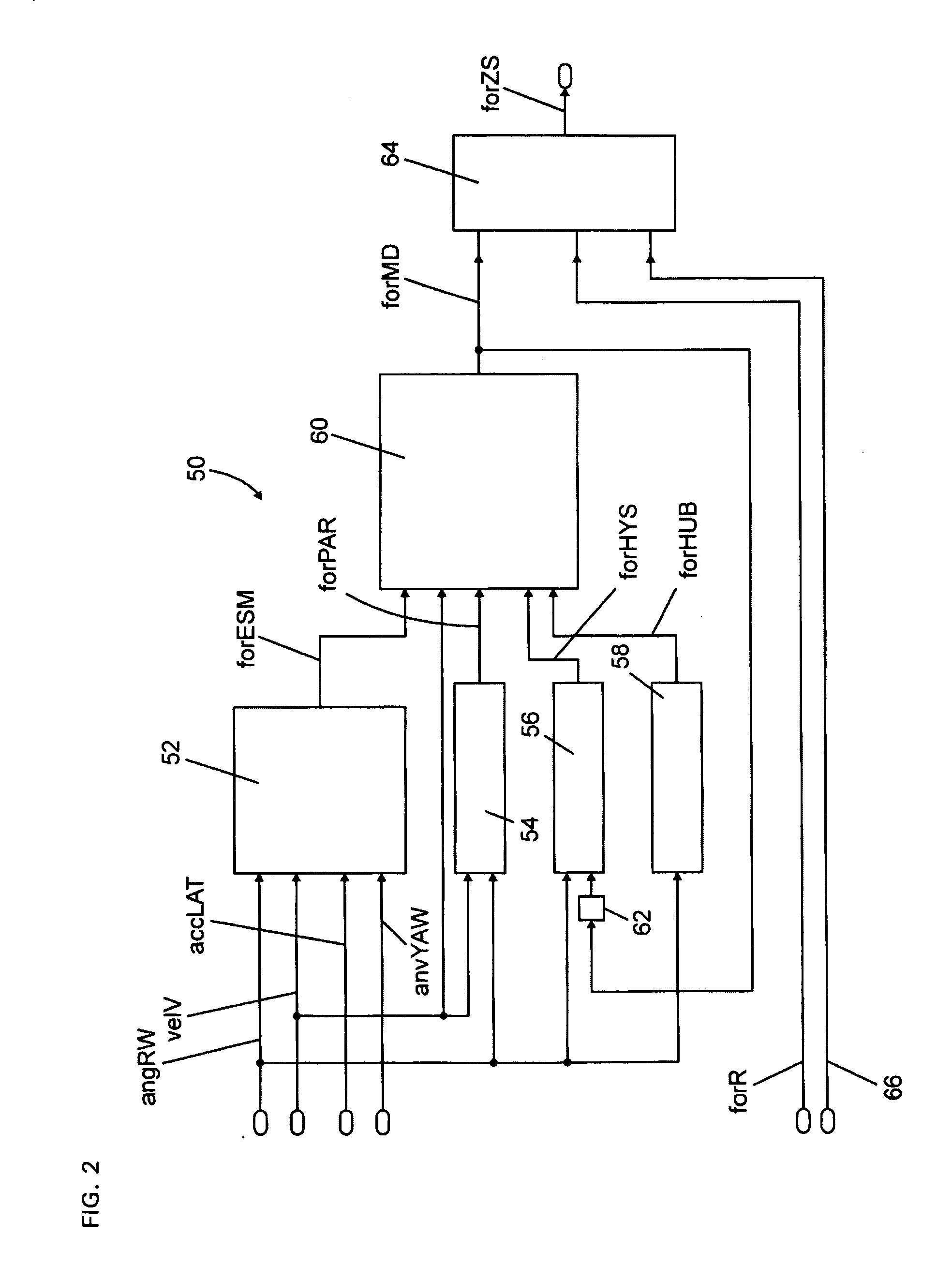
[0014]The invention has the advantage that information, which is reliable to as great an extent as possible, on the behavior of the vehicle or the conditions of the roadway can be transmitted to the driver of the vehicle at all times, even with varying driving situations or operating conditions, by finding the toothed rack force that is employed for generating the driver's desired steering torque as a function of models that have been optimized for the respective driving situation, wherein the toothed rack force is, or individual components of the toothed rack force are, generated by means of the models, as a function of the current driving situation.
[0016]Pursuant to the method according to the invention, the modeled toothed rack force and the actual toothed rack force can additionally be weighted as a function of a driving situation and / or operating variables of the vehicle and can be combined to form a resulting toothed rack force, by means of which the target steering torque can be determined. It is thus possible to adapt the modeled toothed rack force to the actual toothed rack force, so that the modeled toothed rack force according to the invention always corresponds to the actual toothed rack force with sufficient accuracy, for example when the friction coefficient changes, whereby optimal feedback can be provided to the driver at all times, without the disturbances present in the actual toothed rack force negatively influencing the driver's desired torque. This offers an advantage is so much as the modeled toothed rack force according to the invention can be optimally found within a very wide range of possible driving situations. The actual toothed rack force used for the adaptation can be determined by means of a sensor, or alternatively from other variables that characterize the steering device, or the forces acting thereon, and / or actuators.
[0041]A second model comprises variables for describing a vehicle parking process. This process differs significantly from normal driving situations and can, advantageously, be taken into consideration by way of the second model. The second model is activated as the vehicle speed decreases and, accordingly, is deactivated as the vehicle speed increases, wherein the activation and deactivation can be carried out by steadily increasing, or decreasing, the contribution of this component to the modeled toothed rack force. The parking process can, consequently, be determined particularly easily based on the current speed.
[0044]A fourth model describes at least one force, which is generated by raising the vehicle as a function of the wheel angle, and which acts on the toothed rack. This can further improve the modeling process. Depending on the axle construction, the front axle of the vehicle is raised due to the steering process, notably with larger steering angles. This results in a component of the toothed rack force in accordance with a respective steering angle, notably during parking. It is therefore expedient to increase, or reduce, this force component depending on the vehicle speed. This component can thus also be used to generate the force component to be considered during the parking process.
[0048]Modeling can be further improved by adapting the lateral force that acts on the axle of the vehicle, using a modeled lateral force that is found pursuant to a single-track model, an additional lateral force component, and a slip angle. This can be done, for example, by way of various mathematical operations, using non-linearities, and / or by way of controls. The accuracy of the method can thus be improved. It is proposed, in particular, to determine the additional lateral force component using the transverse vehicle acceleration, the yaw velocity and / or yaw acceleration.

Problems solved by technology

Compared to hydraulic steering systems, however, such EPS steering systems have disadvantages in terms of the feedback regarding the driving conditions.
Additional disturbances can develop as a result of longitudinal dynamics events at the steered front axle.

Method used


Image

  • Method for determining a toothed rack force for a steering device in a vehicle
  • Method for determining a toothed rack force for a steering device in a vehicle
  • Method for determining a toothed rack force for a steering device in a vehicle

Examples


Embodiment Construction

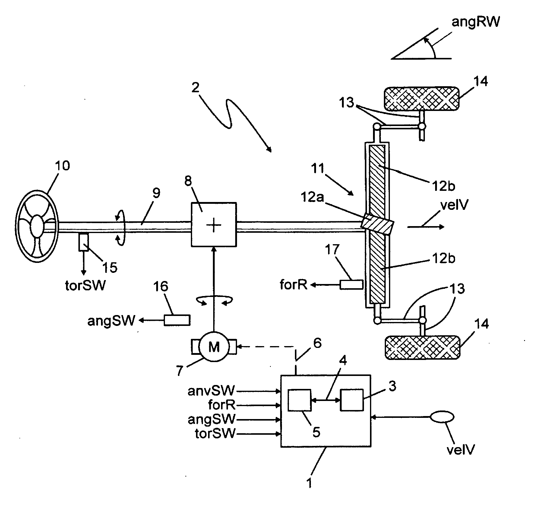
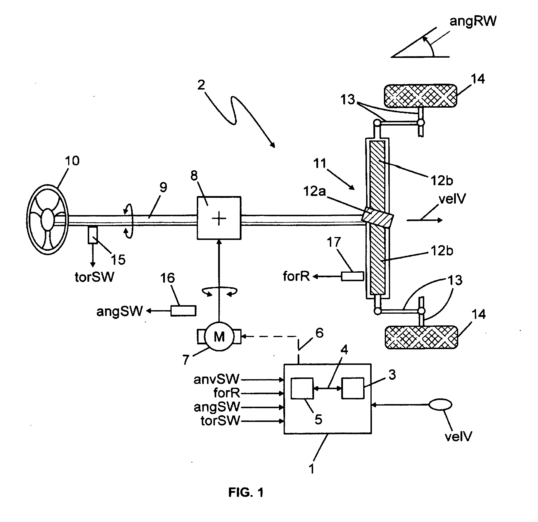
[0054]The control unit is also referred to hereinafter as a “controller”.

[0055]FIG. 1 shows a controller 1, which is associated with a steering device 2. A microprocessor 3 is disposed in the controller 1 and is connected via a data line 4, such as a bus system, to a memory medium 5. The controller 1 is connected, via a signal line 6, to a motor 7, such as an electric motor, allowing for control of the power of the motor 7 by the controller 1. The motor 7 acts on a torsion bar 9 via a transmission 8. A steering means 10, which in the present example is designed as a steering wheel, is disposed on the torsion bar 9 and can be used to apply a torque to the torsion bar 9 as a result of a driver actuating the steering means 10.

[0056]The steering device 2 moreover comprises a steering gear 11, which is designed, for example, as a rack-and-pinion steering gear. The steering gear 11 can further be designed as a ball-and-nut gear or recirculating-ball gear. The description hereafter primari...


PUM


Abstract

Disclosed is a method for determining a toothed rack force on a steering device in a vehicle, wherein the toothed rack force (forZS) is determined as a function of a plurality of models, and wherein a component (forESM) of the toothed rack force (forZS) which relates to a driving process is generated by means of a first model, and a component of the toothed rack force (forZS) which relates to a parking process is generated by means of a second model.

Description

BACKGROUND OF THE INVENTION[0001]The invention relates to a method for determining a toothed rack force for a steering device in a vehicle.[0002]The invention also relates to a steering device in the vehicle. The invention further relates to a control unit for a steering device in a vehicle and to a computer program that can be executed on the control unit.[0003]In modern steering devices, for example in an electric power steering (EPS) system or in what is referred to as a Steer-by-Wire (SbW) steering system, a target steering torque is determined, which is applied to a steering means, for example a steering wheel, in order to support or counteract the force applied by the driver.[0004]EPS steering systems that are currently employed generate an EPS motor torque based on a toothed rack force that is present, so as to provide the driver with the appropriate steering assistance. The toothed rack force is decisively influenced by the current cornering forces. A significant part of the...

Claims


Application Information

Patent Timeline
IPC IPC(8): B62D6/00G01M17/06
CPCB62D5/0472G01L5/221B62D6/008
Inventor STRECKER, JOERGWERNER, THOMAS
Owner ROBERT BOSCH AUTOMOTIVE STEERING
Learn More