
Circuit and method to suppress the parasitic resonance from a dc/dc converter

a parasitic resonance and circuit technology, applied in the field of suppressing circuits, can solve the problems of synchronous buck converters having undesirable phase voltage ringing, generating broadband noise, and unable to meet the needs of synchronous buck converters, so as to reduce the ringing of voltag

Inactive Publication Date: 2012-03-01
UNIVERSITY OF MISSOURI
View PDF4 Cites 29 Cited by
  • Summary
  • Abstract
  • Description
  • Claims
  • Application Information

AI Technical Summary

Benefits of technology

[0007]Embodiments of the present invention solve the above-mentioned problems and provide a distinct advance in the art of electric voltage conversion circuits. More particularly, embodiments of the invention provide snubber circuits that reduce the parasitic resonance in DC / DC conversion circuits.
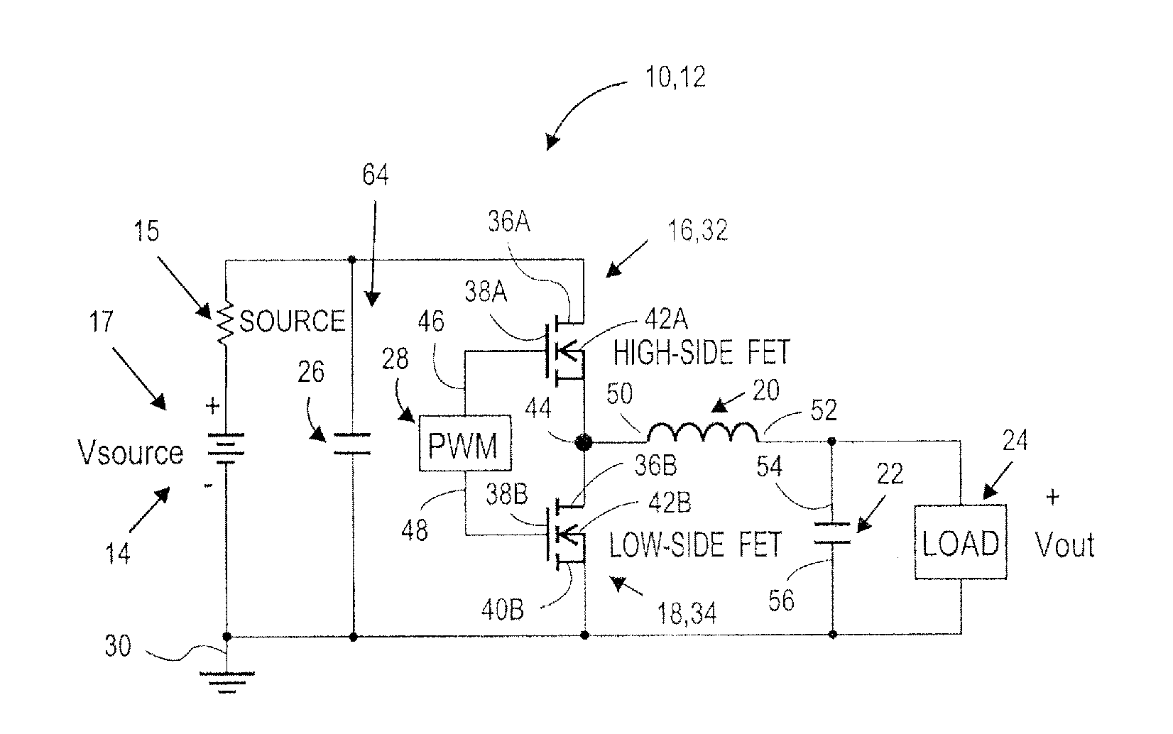
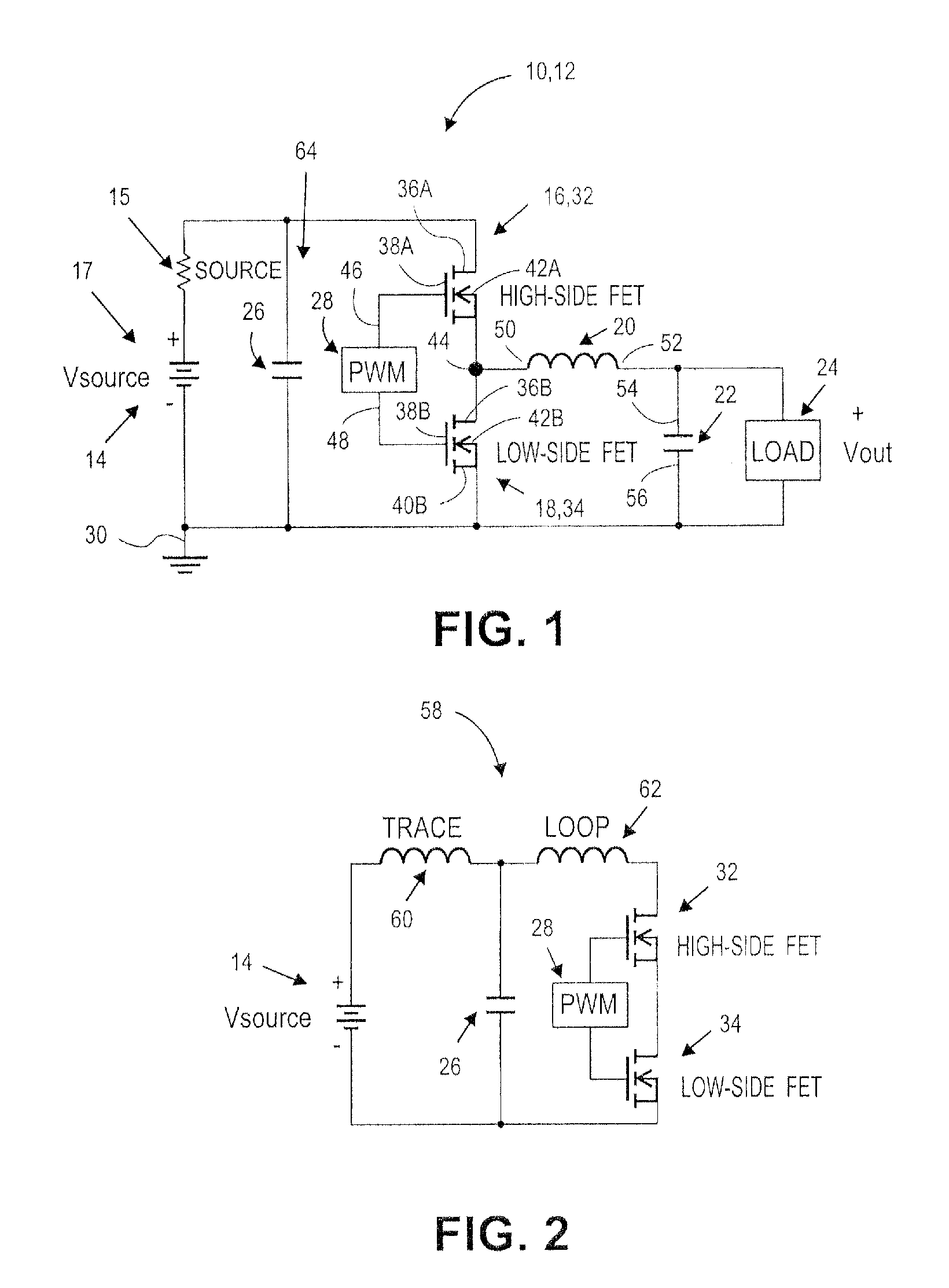
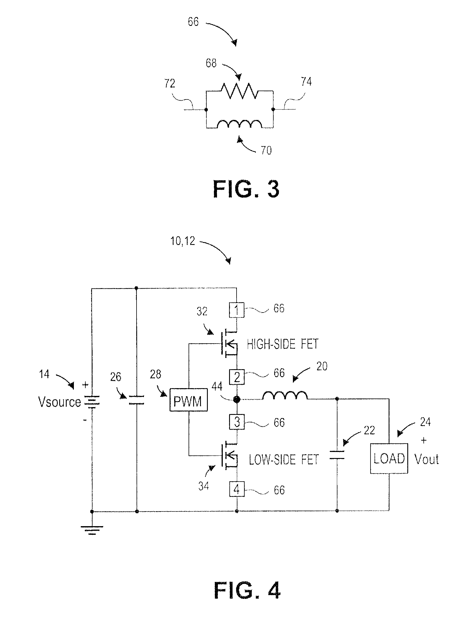
[0008]Embodiments of the present invention provide a snubber circuit for use with a DC / DC converter. The snubber circuit may broadly comprise a snubber resistor connected in parallel with a snubber inductor. The DC / DC converter may include a voltage source, a first switching element, a second switching element, an output inductor, and an output capacitor. The voltage source may include a positive terminal and a negative terminal connected to a ground node. The first switching element may include a first terminal connected to the positive terminal of the voltage source. The second switching element may be connected to a second terminal of the first switching element. The series combination of the output inductor and the output capacitor may be connected between the second terminal of the first switching element and the ground node. The snubber circuit may be connected between the second switching element and the ground node and may reduce a ringing of a voltage between the second terminal of the first switching element and the ground node.

Problems solved by technology

However, the voltage divider network may lack efficiency since some of the input energy is lost as heat through the resistive elements.
However, when metal-oxide semiconductor field-effect transistors (MOSFETs) , for example, are utilized as the switching elements, there may be a parasitic resonance formed by the loop of the input capacitance of one MOSFET being on and conductive and the other MOSFET being off and open, thus acting as a capacitance.
The parasitic resonance may cause the synchronous buck converter to have undesirable phase voltage ringing and to generate broadband noise in the 50 Megahertz (MHz) to 300 MHz range.

Method used


Image

  • Circuit and method to suppress the parasitic resonance from a dc/dc converter
  • Circuit and method to suppress the parasitic resonance from a dc/dc converter
  • Circuit and method to suppress the parasitic resonance from a dc/dc converter

Examples


Embodiment Construction

[0020]The following detailed description of the invention references the accompanying drawings that illustrate specific embodiments in which the invention can be practiced. The embodiments are intended to describe aspects of the invention in sufficient detail to enable those skilled in the art to practice the invention. Other embodiments can be utilized and changes can be made without departing from the scope of the present invention. The following detailed description is, therefore, not to be taken in a limiting sense. The scope of the present invention is defined only by the appended claims, along with the full scope of equivalents to which such claims are entitled.

[0021]In this description, references to “one embodiment”, “an embodiment”, or “embodiments” mean that the feature or features being referred to are included in at least one embodiment of the technology. Separate references to “one embodiment”, “an embodiment”, or “embodiments” in this description do not necessarily ref...


PUM

PropertyMeasurementUnit
voltageaaaaaaaaaa
voltageaaaaaaaaaa
voltageaaaaaaaaaa

Abstract

A snubber circuit for use with a DC / DC converter broadly comprises a snubber resistor connected in parallel with a snubber inductor. The DC / DC converter may include a voltage source, a first switching element, a second switching element, an output inductor, and an output capacitor. The voltage source may include a positive terminal and a negative terminal connected to a ground node. The first switching element may include a first terminal connected to the positive terminal of the voltage source The second switching element may be connected to a second terminal of the first switching element. The series combination of the output inductor and the output capacitor may be connected between the second terminal of the first switching element and the ground node. The snubber circuit may be connected between the second switching element and the ground node.

Description

RELATED APPLICATION[0001]The present application claims the priority benefit of U.S. Provisional Application No. 61 / 176,409, entitled “METHOD TO SUPPRESS THE PARASITIC RESONANCE IN SWITCHING CIRCUITS USING PARALLEL RESISTOR AND INDUCTOR COMBINATION,” filed May 7, 2009. The identified provisional application is incorporated herein by specific reference.BACKGROUND OF THE INVENTION[0002]1. Field of the Invention[0003]Embodiments of the present invention relate to electric voltage conversion circuits. More particularly, embodiments of the present invention relate to snubber circuits that reduce the parasitic resonance in DC / DC conversion circuits.[0004]2. Description of the Related Art[0005]Electric voltage conversion circuits generally convert the level of voltage from a voltage source to the level of voltage required by a load. Voltage conversion circuits may work with alternating current (AC) voltage or direct current (DC) voltage and may convert the level of voltage up, by increasin...

Claims


Application Information

Patent Timeline
Patent Type & Authority Applications(United States)
IPC IPC(8): G05F3/08H01F41/02
CPCH02M1/34Y10T29/4902H02M2001/348H02M1/348
Inventor POMMERENKE, DAVIDKAM, KEONGBHARGAVA, ANKITSHAO, PENGCHANG, XINLI, HONGYU
Owner UNIVERSITY OF MISSOURI
Learn More