
Planar lightwave fourier-transform spectrometer measurement including phase shifting for error correction

a fourier-transform spectrometer and phase shifting technology, applied in the field of planar lightwave circuits, can solve the problem that the actual optical delay of the fabricated mzis is likely to deviate from the design value, and achieve the effect of reducing the cost of fabricated mzis

Active Publication Date: 2012-03-01
GUNMA UNIVERSITY +1
View PDF5 Cites 16 Cited by
  • Summary
  • Abstract
  • Description
  • Claims
  • Application Information

AI Technical Summary

Benefits of technology

[0016]FIG. 5 is a schematic view of a configuration of the spectrometer using a phase shift technique in accordance with the present...

Problems solved by technology

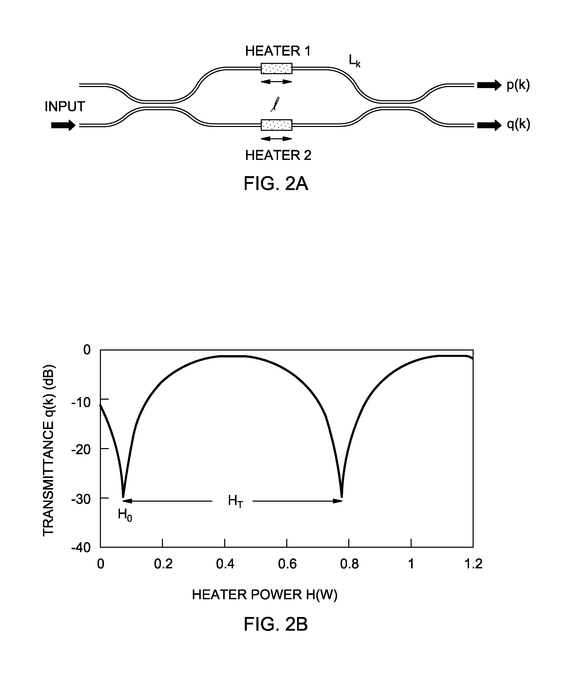
The actual optical delays of the fabricated MZIs are likely to deviate from their designed values and the phase error frozen in each MZI may prevent one from producing the correct spectrum.

Method used


Image

  • Planar lightwave fourier-transform spectrometer measurement including phase shifting for error correction
  • Planar lightwave fourier-transform spectrometer measurement including phase shifting for error correction
  • Planar lightwave fourier-transform spectrometer measurement including phase shifting for error correction

Examples


Embodiment Construction

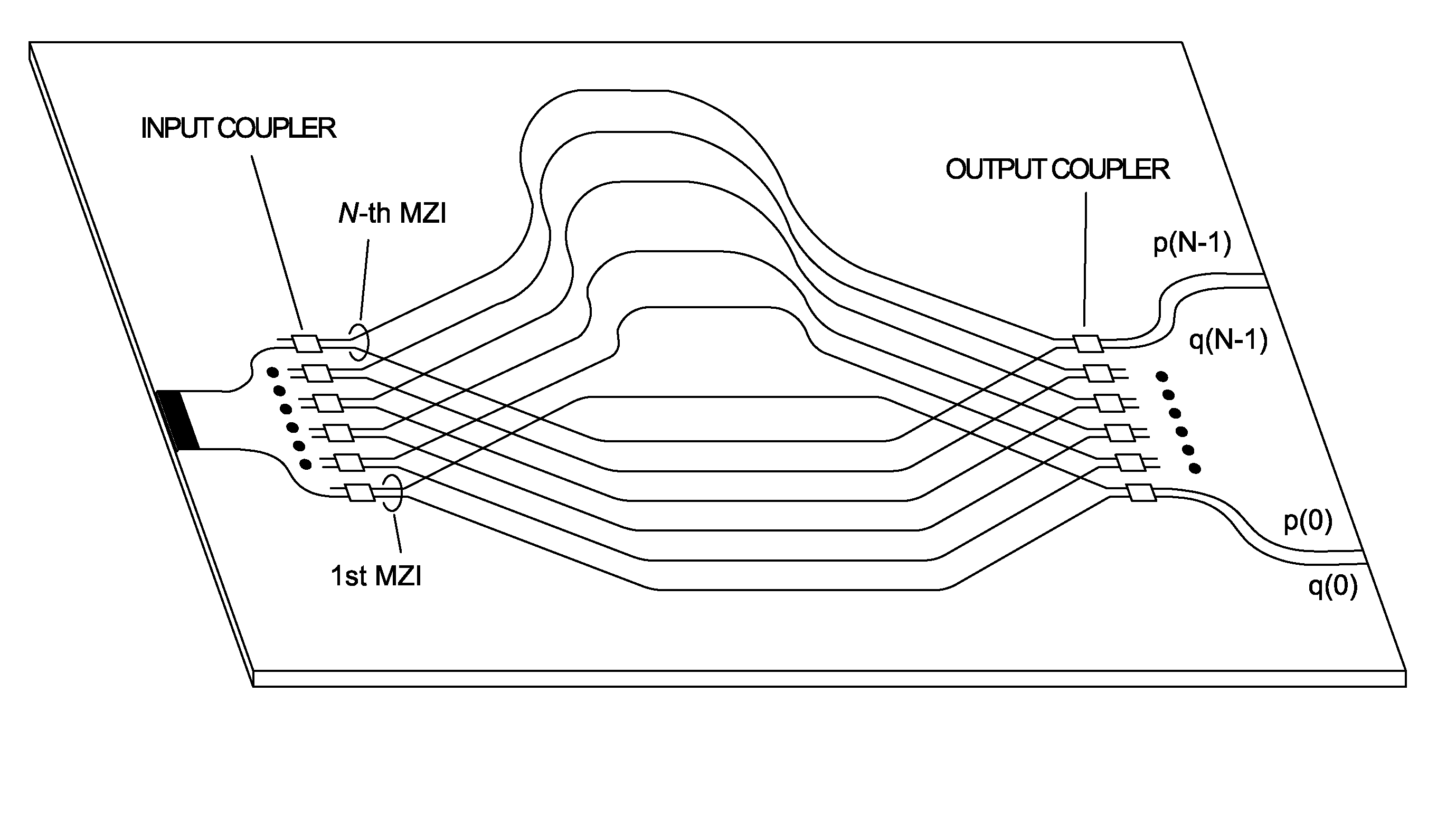
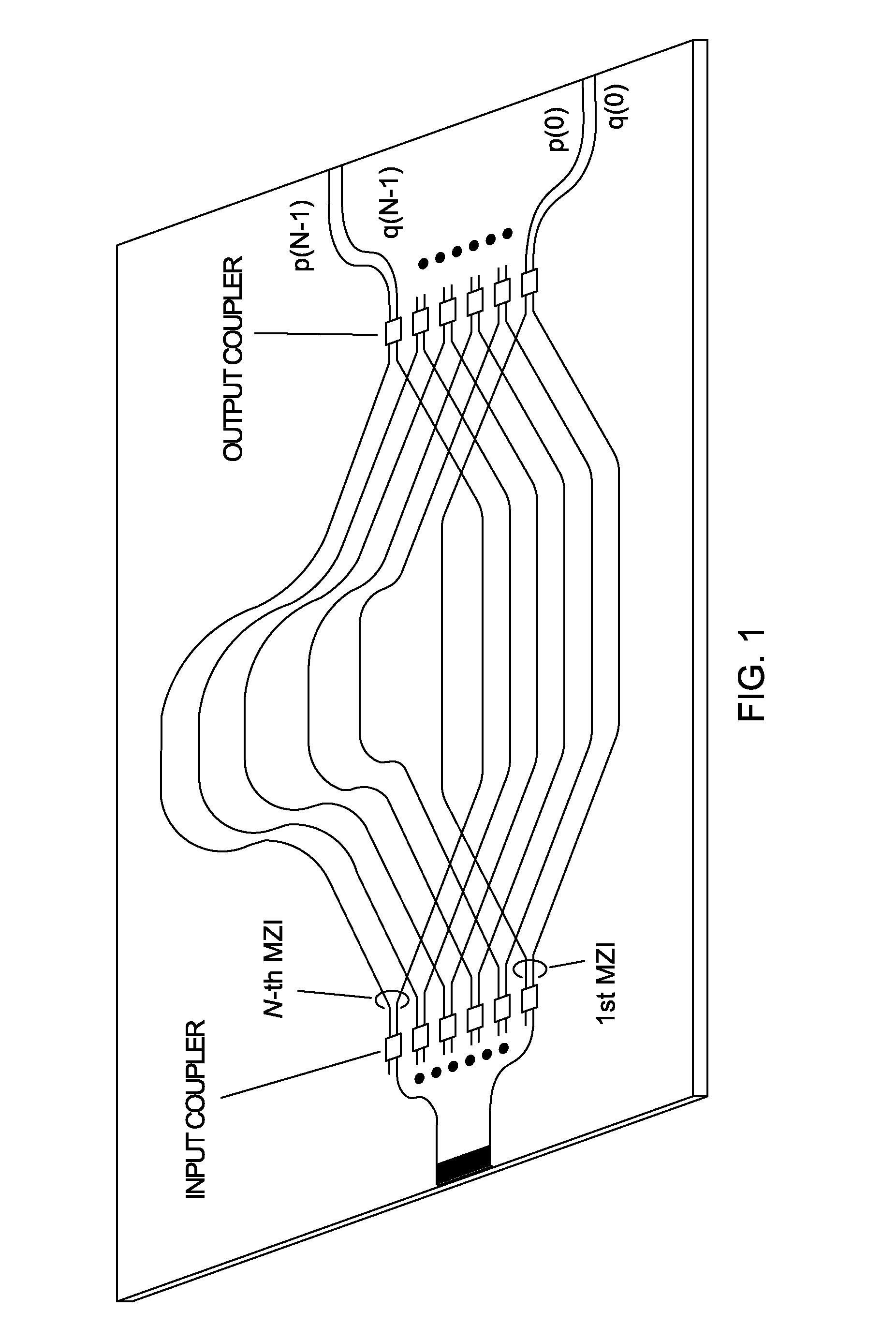
[0019]FIG. 1 is a schematic of a PLC spectrometer configuration having an interleaved MZI array. The total number of MZIs is N and path length difference increment is ΔL=162 μm. The waveguide core size in this example is 4.5×4.5 μm2 with a 1.5% refractive-index difference. The minimum bend radius is 2 mm. White boxes indicate 3-dB couplers consisting of either directional couplers or multimode interference couplers. Waveguide arms in the MZIs may be intentionally inclined to both sides so that the waveguides intersect by more than 45° with each other. The excess loss of the waveguide crossing can be reduced as low as ˜0.02 dB / intersection when the crossing angle is larger than 45°. Dummy crossing waveguides can also be placed to make the total number of waveguide crossing equal for all MZIs. Both cross port and through port outputs p(k) and q(k) in the k-th (k=0˜N−1) MZI can be measured so that the spatial non-uniformity of the input light distribution can be corrected. For a signal...


PUM


Abstract

A transform spectrometer measurement apparatus and method for a planar waveguide circuit (PLC). The spectrometer typically includes an input optical signal waveguide carrying an input optical signal; a plurality of couplers, each connected to the input optical signal waveguide, and each including a coupler output for carrying a coupled optical signal related to the input optical signal; and an array of interleaved, waveguide Mach-Zehnder interferometers (MZI), each having at least one input MZI waveguide, each MZI input waveguide receiving a coupled optical signal from a respective coupler output. A phase shifting circuit is applied to at least one arm of the MZIs to induce an active phase shift on the arm to thereby measure phase error in the MZIs. Light output from the MZIs is measured under intrinsic phase error conditions and after an active phase shift by the phase shifting circuit.

Description

RELATED APPLICATION INFORMATION[0001]This application claims priority to U.S. Provisional Patent Application entitled PLANAR LIGHTWAVE FOURIER-TRANSFORM SPECTROMETER INCLUDING PHASE SHIFTING FOR ERROR CORRECTION, filed Jul. 28, 2010, as Ser. No. 61 / 368,419, which application is hereby incorporated by reference herein in its entirety. This application is also related to U.S. patent application entitled PLANAR LIGHTWAVE FOURIER-TRANSFORM SPECTROMETER, filed Feb. 23, 2010, as Ser. No. 12 / 710,765, which Application is also hereby incorporated herein by reference in its entirety.TECHNICAL FIELD[0002]The present invention relates in general to planar lightwave circuits. More particularly, the present invention relates to a planar lightwave, Fourier-transform spectrometer measurement apparatus and method.BACKGROUND OF THE INVENTION[0003]High-resolution and miniaturized spectrometers without moving parts have a great potential for use in optical fiber communication networks, environmental s...

Claims


Application Information

Patent Timeline
IPC IPC(8): G01J3/45
CPCG01J3/45G01J3/4532G01J3/4531
Inventor TAKADA, KAZUMASAOKAMOTO, KATSUNARI
Owner GUNMA UNIVERSITY
Learn More