Wireless communication terminal and wireless communication method

a wireless communication and terminal technology, applied in the field of wireless communication terminals and wireless communication methods, can solve the problems of transmission signal to reception signal self-interference, and achieve the effect of satisfactory precision and measurement of the channel quality of adjacent cells

Inactive Publication Date: 2012-03-01
PANASONIC CORP
View PDF1 Cites 13 Cited by
  • Summary
  • Abstract
  • Description
  • Claims
  • Application Information

AI Technical Summary

Benefits of technology

[0028]According to the wireless communication terminal and the wireless communication method of the invention, it is possible to measure the channel quality of an adjacent cell with satisfactory precision without interference of a current cell.

Problems solved by technology

When the backhaul channel and the access channel are covered in the same frequency band, if RN performs transmission and reception simultaneously, self interference from transmission signal to reception signal occurs.
However, in the subframes [n+2, n+6] in which RN serves as backhaul, if RN does not transmit a signal from eNB, a measurement operation to measure the quality of RN is not performed in a wireless communication terminal of LTE which does not know the presence of RN.

Method used


Image

  • Wireless communication terminal and wireless communication method
  • Wireless communication terminal and wireless communication method
  • Wireless communication terminal and wireless communication method

Examples


example 2

[0072](Specific Example 2 of CoMP: JT)

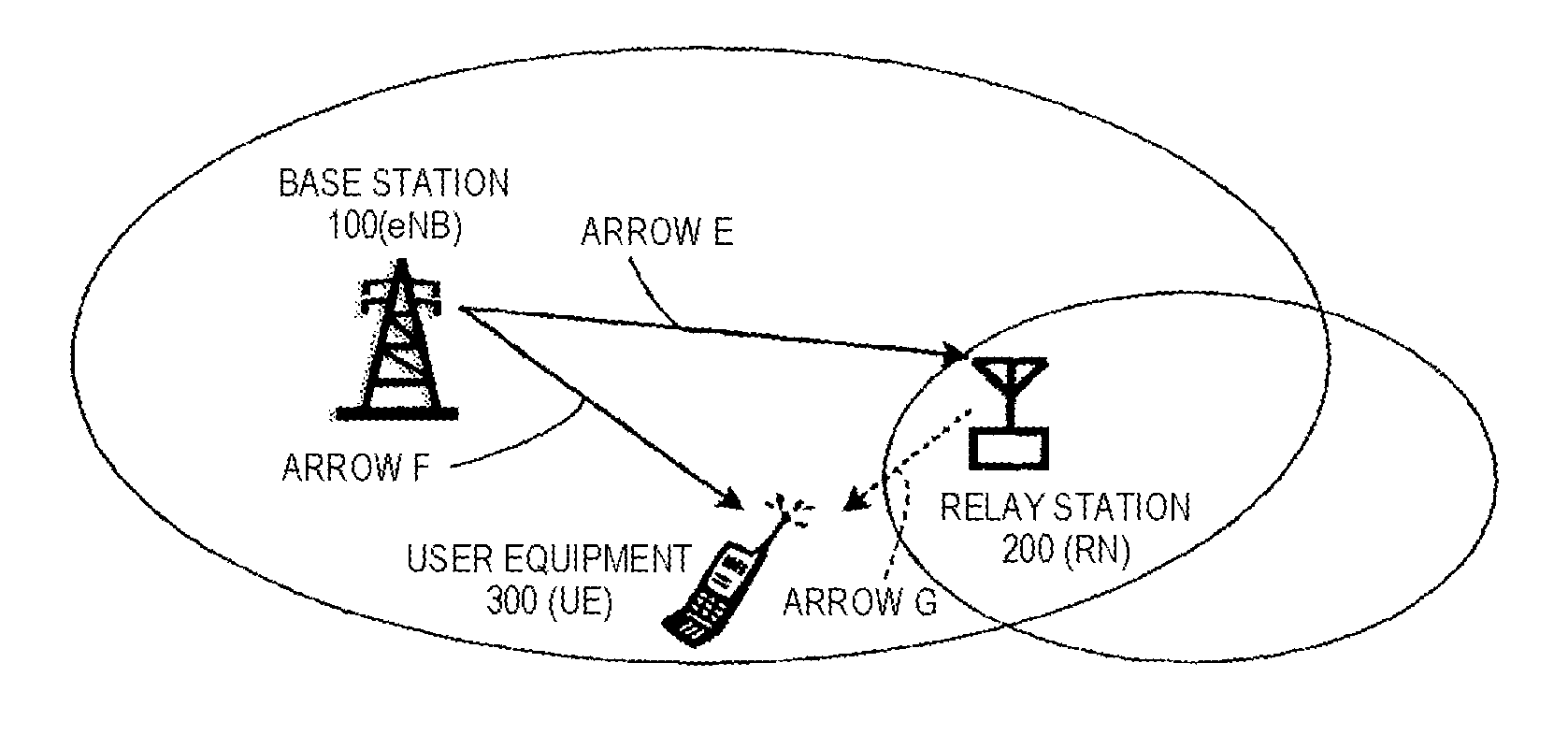
[0073]Next, a case regarding JT is described. JT can be realized by transmitting the same signal from RN and eNB to which RN is connected simultaneously and combining the signals in UE.

[0074]In LTE-A, similarly to a case where “the MBSFN subframe to be used as backhaul by RN” is used, a method of realizing the above-described JT in the MBSFN subframe is studied. This is because, when JT is performed, it is necessary to make the reference signals of a plurality of cells to be transmitted simultaneously, and in a normal subframe, there is an influence on a cell-specific reference signal. Hereinafter, an MBSFN subframe which realizes JT is referred to as “an MBSFN subframe to be used in CoMP” and distinguished from “the MBSFN subframe to be used as backhaul by RN”.

[0075]In LTE-A, information for distinguishing “MBSFN subframe to be used as backhaul by RN” and “the MBSFN subframe to be used in CoMP” from each other is notified from RN to UE, UE of L...

first embodiment

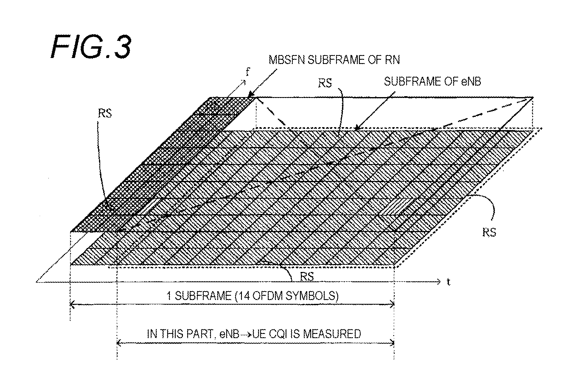
[0135]Next, as in the first embodiment, UE under RN1 provides a channel quality measurement mode in which the channel quality is measured using a region since the third symbol excluding the top two symbols in the subframe. In one RN, the channel quality from another RN to UE is measured in “the MBSFN subframe to be used as backhaul by RN”.

[0136]For example, the wireless communication environment which is assumed in FIGS. 8 and 9 is described. In the subframes [n+2, n+6] serving as the MBSFN subframe which is used as backhaul by the subframe of RN1, UE measures the channel quality from RN2 to UE, and in the subframe [n+2] serving as the MBSFN subframe which is used as backhaul by the subframe of RN2, UE measures the channel quality from RN1 to UE.

[0137]In the modification of the embodiment, the measurement method of the CQI for CoMP described with reference to FIGS. 8 and 9 is used, in UE under RN, it is possible to measure the channel quality of one RN with satisfactory precision wi...


PUM


Abstract

To measure the channel quality of adjacent cells with satisfactory precision without interference of a current cell. A wireless communication terminal of the invention is connected to a relay station and configured to receive data from at least one of the relay station, a base station, and another relay station different from the relay station. The wireless communication terminal includes a receiver which receives a signal including control information for measuring the channel quality of the non-connected base station or another non-connected relay station from the connected relay station, an extractor which extracts the control information from the signal received by the receiver, a measurement section which measures the channel quality of the non-connected base station or non-connected another relay station in a region, in which the connected relay station does not transmit other signals to the wireless communication terminal, on the basis of the control information, and a transmitter which transmits the measurement result of the channel quality of the non-connected base station or another non-connected relay station measured by the measurement section to the connected relay station.

Description

TECHNICAL FIELD[0001]The present invention relates to a wireless communication terminal which is connected to a base station, and transmits and receives data with respect to the base station, and a wireless communication method.BACKGROUND ART[0002]In the 3GPP (3rd Generation Partnership Project) which is the international standards organization of mobile communication, the standardization of LTE-Advanced (Long Term Evolution-Advanced, LTE-A) of a fourth-generation mobile communication system has started. In LTE-A, as described in Non Patent Literature 1, for the purpose of coverage expansion or capacity improvement, a relay technique is studied in which a radio signal is relayed using a relay station (Relay Node). For the purpose of cell edge throughput improvement, CoMP (Coordinated multiple point transmission and reception) is also studied in which a plurality of nodes are coordinated to transmit and receive data.[0003]The relay technique is described with reference to FIG. 13. FI...

Claims


Application Information

Patent Timeline
Patent Type & Authority Applications(United States)
IPC IPC(8): H04B7/14H04W24/00H04L12/26
CPCH04B7/2606H04W84/047H04W72/085H04W24/10H04W72/542
Inventor YUDA, YASUAKINAKAO, SEIGOIMAMURA, DAICHIHORIUCHI, AYAKO
Owner PANASONIC CORP
Why Eureka
Try Eureka