Motion capture element mount

a technology of motion capture and element mount, which is applied in the field of mounts, can solve problems such as known systems, and achieve the effects of minimizing overall instrumented versus non-instrumented weight differences, preventing electrical conductivity loss, and minimizing weight differences

Active Publication Date: 2012-03-01
NEWLIGHT CAPITAL LLC
View PDF14 Cites 56 Cited by
  • Summary
  • Abstract
  • Description
  • Claims
  • Application Information

AI Technical Summary

Benefits of technology

[0013]If the electronics package is installed, then generally a positive battery contact, printed circuit board (PCB), an insulator or insulative spacer, with negative electrical contact and battery may be installed between the shaft enclosure and cap. The electronics that may be coupled with the PCB for example may include active motion capture electronics that are battery powered, passive or active shot count components, for example a passive or active radio frequency identification (RFID) tag. Embodiments of the electronics may include motion capture accelerometers and/or gyroscopes and/or an inertial measurement unit along with wireless transmitter/receiver or transceiver components. The RFID tag enables golf shots for each club associated with a golfer to be counted. Golf shots may optionally be counted via an identifier associated with motion capture electronics on the golf club in conjunction with a mobile computer, for example an IPHONE® equipped with an RFID reader that concentrates the processing for golf shot counting on the mobile computer instead of on each golf club. Optionally a wireless antenna may be coupled with the cap or alternatively may be implemented integral to the PCB as desired. One or more embodiments of the invention may also include a Global Positioning System (GPS) antenna. The GPS antenna may be mounted on the printed circuit board or may be located separate from the printed circuit board. One or more embodiments of the invention may also directly or indirectly communicate with any other sensors coupled with the club including motion analysis capture elements, strain gauges or any other type of sensor coupled for example with the golf club head. One or more embodiments of the invention may also utilize a battery coupling that attaches the batter...

Problems solved by technology

Other mounts combine the electronics on the mount itself in a monolithic package that does not allow for the weight of the club to remain constant with or without electronics ...

Method used


Image

  • Motion capture element mount
  • Motion capture element mount
  • Motion capture element mount

Examples


Embodiment Construction

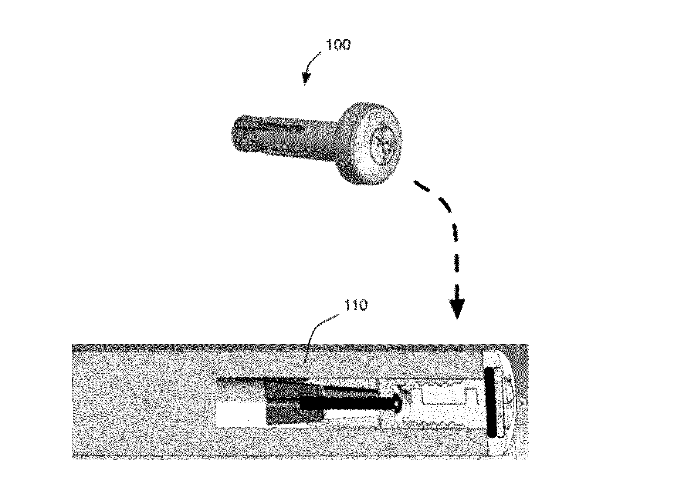
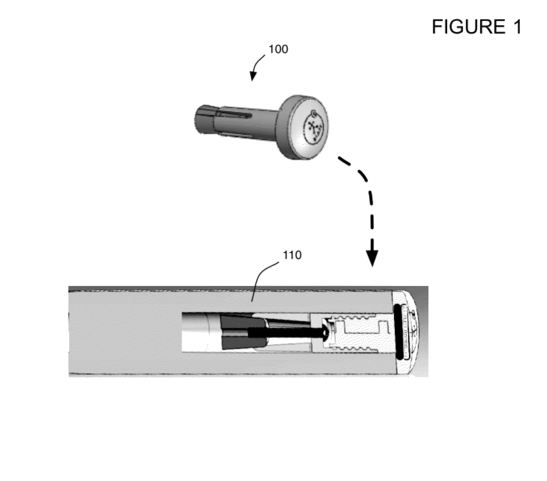
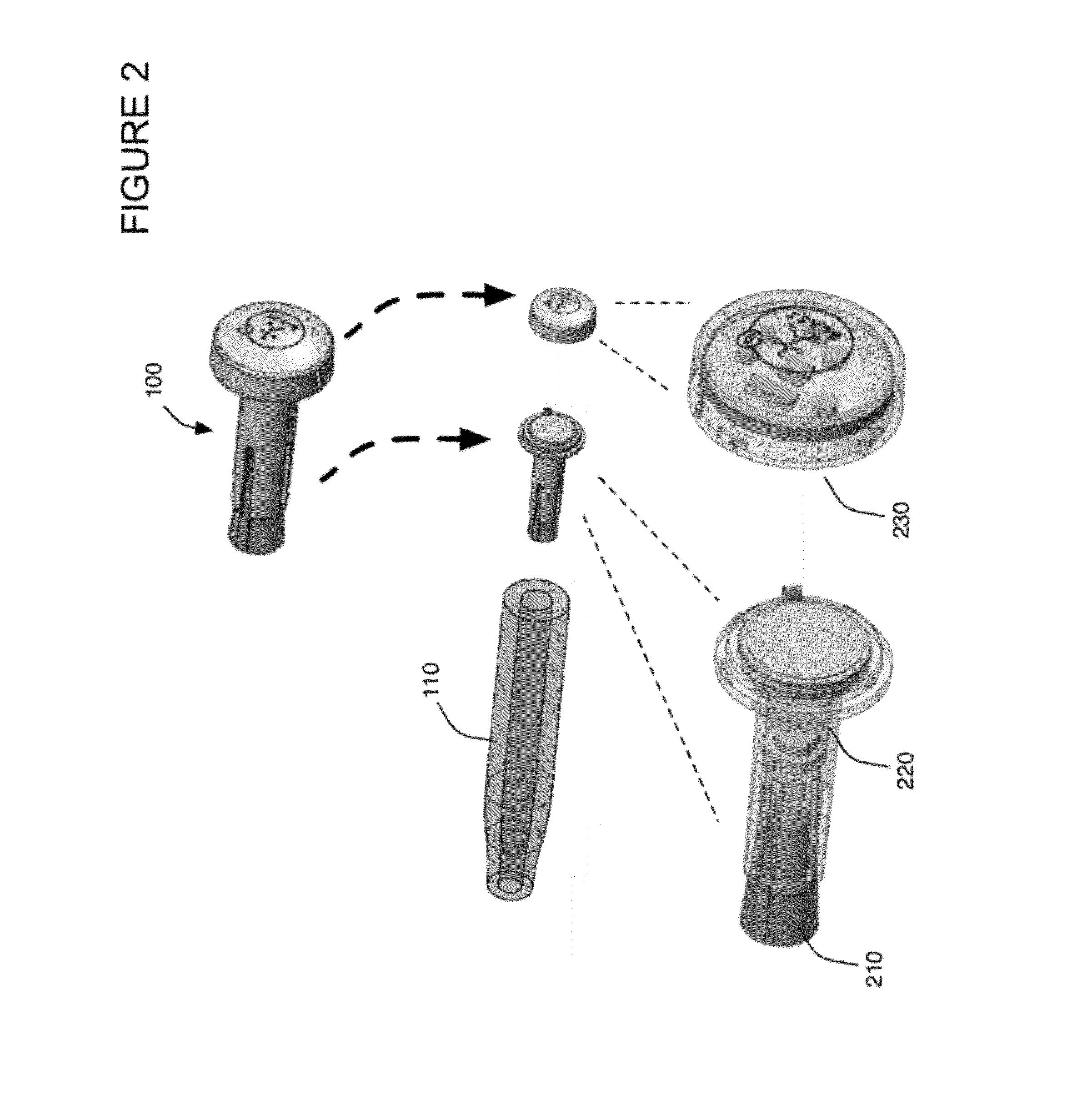
[0041]A motion capture element mount will now be described. In the following exemplary description numerous specific details are set forth in order to provide a more thorough understanding of the ideas described throughout this specification. It will be apparent, however, to an artisan of ordinary skill that embodiments of ideas described herein may be practiced without incorporating all aspects of the specific details described herein. In other instances, specific aspects well known to those of ordinary skill in the art have not been described in detail so as not to obscure the disclosure. Readers should note that although examples of the innovative concepts are set forth throughout this disclosure, the claims, and the full scope of any equivalents, are what define the invention. Although this disclosure refers to an exemplary piece of equipment such as a golf club, one skilled in the art will recognize that embodiments of the invention may be utilized in any equipment capable of c...


PUM


Abstract

Enables coupling or retrofitting a golf club with active motion capture electronics that are battery powered, passive or active shot count components, for example a passive RFID, and/or a visual marker on the cap for use with visual motion capture cameras. Does not require modifying the golf club. Electronics package and battery can be easily removed and replaced, for example without any tools. May utilize a weight that is removed when inserting the electronic package in the mount, wherein the weight element may have the same weight as an electronics package, for no net change or minimal change in club weight. May be implemented with a shaft enclosure and expander that may be coupled with a screw aligned along an axis parallel to the axis of the golf club shaft. May utilize non-permanently and/or friction coupling between the mount and golf club shaft. Cap may include a visual marker and/or logo.

Description

[0001]This application is a continuation-in-part of U.S. Utility patent application Ser. No. 13 / 048,850 filed 15 Mar. 2011, which is a continuation-in-part of U.S. Utility patent application Ser. No. 12 / 901,806 filed 11 Oct. 2010, which is a continuation-in-part of U.S. Utility patent application Ser. No. 12 / 868,882 filed 26 Aug. 2010, the specifications of which are hereby incorporated herein by reference.BACKGROUND OF THE INVENTION[0002]1. Field of the Invention[0003]One or more embodiments setting forth the ideas described throughout this disclosure pertain to the field of mounts as utilized in sporting equipment for electronics and visual markers. More particularly, but not by way of limitation, one or more aspects of the disclosure enable a motion capture element mount.[0004]2. Description of the Related Art[0005]Known systems for mounting electronics on sporting equipment include mounts in the shafts of fishing poles, and golf clubs for example. Existing mounts have the follow...

Claims


Application Information

Patent Timeline
IPC IPC(8): A63B69/36A63B26/00A63B69/38
CPCA63B2220/12G01S19/19A63B69/36A63B69/3611A63B2225/15A63B2220/17A63B21/0724A63B2225/685A63B21/1465A63B2207/02A63B2225/54A63B2220/807A63B53/14A63B2071/0694A63B2220/05A63B2210/50A63B2220/40A63B21/4033A63B2225/74A63B60/16
Inventor BENTLEY, MICHAEL
Owner NEWLIGHT CAPITAL LLC
Why Eureka
Try Eureka