
Control system for internal combustion engine

a control system and internal combustion engine technology, applied in the direction of electrical control, process and machine control, instruments, etc., can solve the problem of large manpower required for setting tables or maps, and achieve the effect of accurate torque related parameters and simple methods

Active Publication Date: 2012-03-01
HONDA MOTOR CO LTD
View PDF10 Cites 13 Cited by
  • Summary
  • Abstract
  • Description
  • Claims
  • Application Information

AI Technical Summary

Benefits of technology

[0010]The present invention is made contemplating the above-described point, and an objective of the invention is to provide a control system for an internal combustion engine, which can accurately calculate the torque related parameter which is necessary in the torque demand control according to the exhaust gas recirculation ratio by a comparatively simple method.
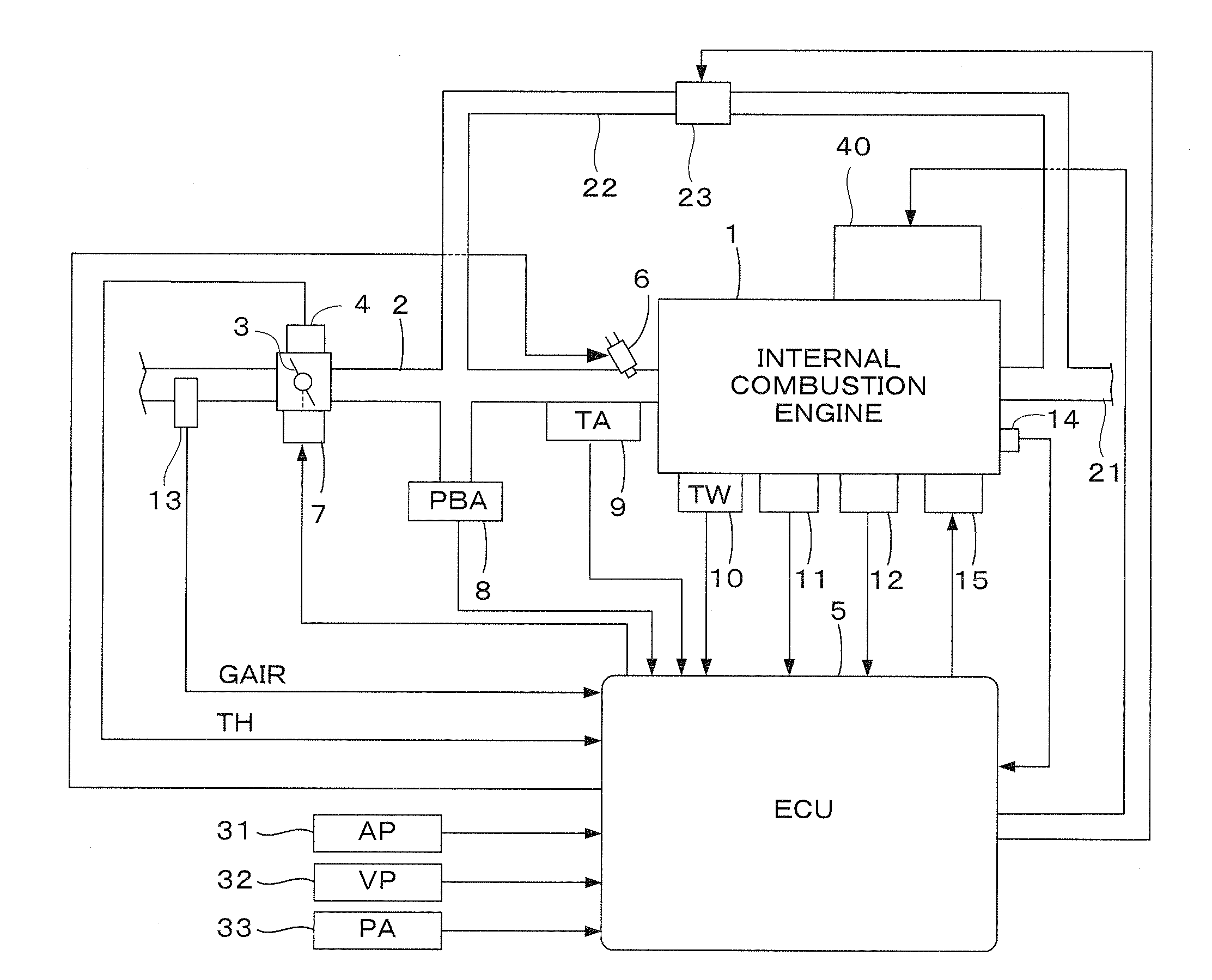
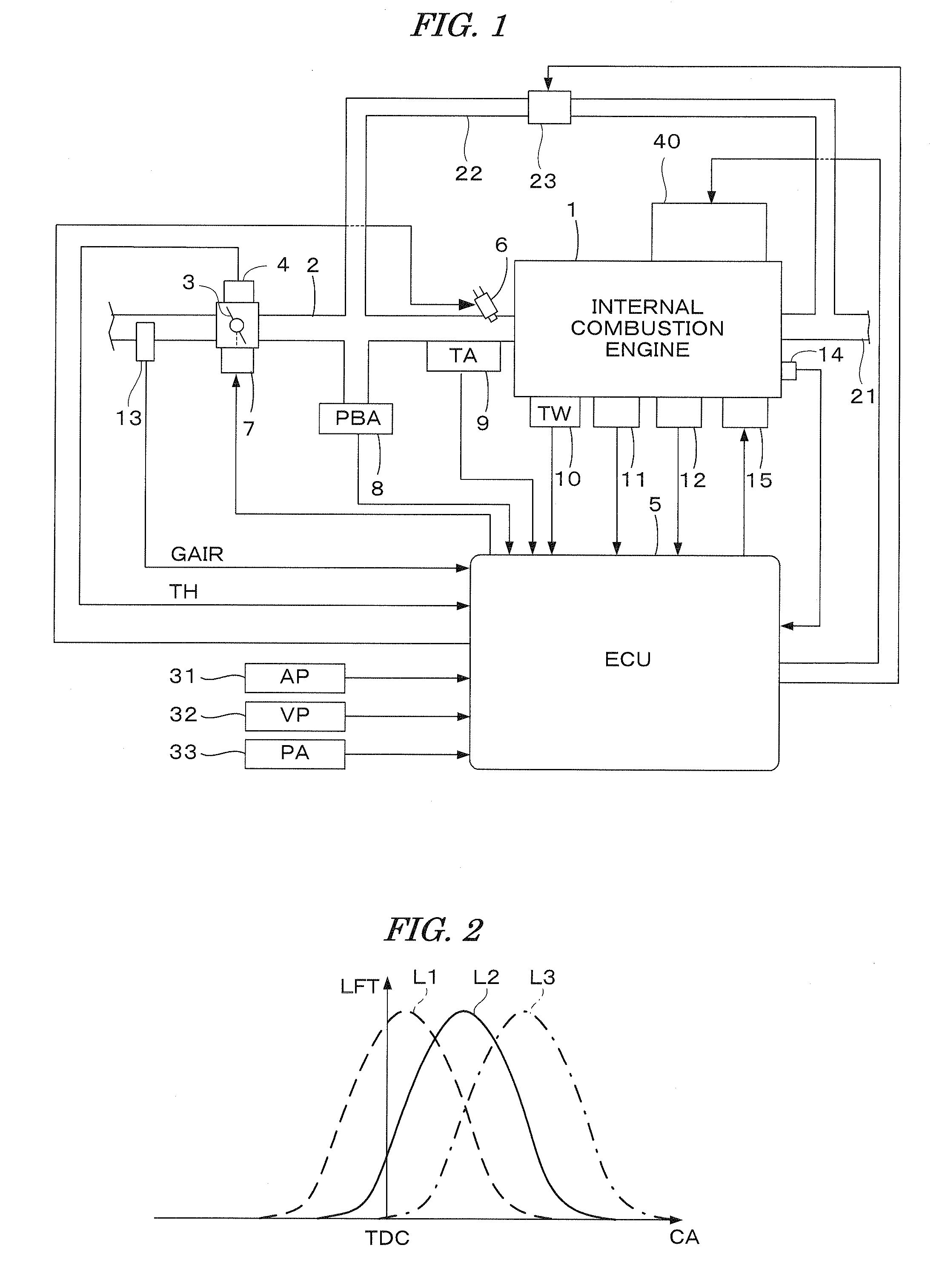
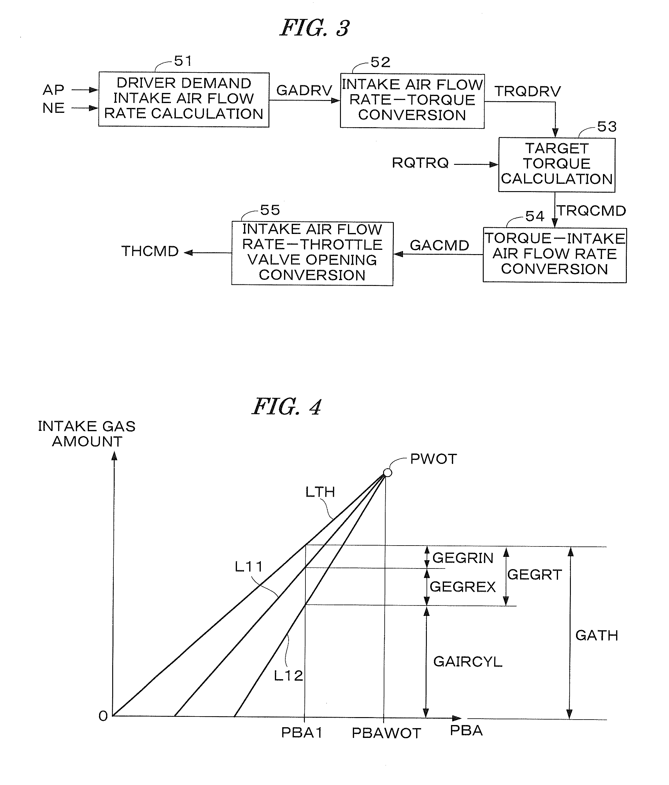
[0012]With this configuration, the target intake air amount of the engine is calculated; the wide-open intake air amount, which is an intake air amount corresponding to the state where the throttle valve is fully opened, is calculated according to the engine rotational speed; the theoretical intake air amount corresponding to the state where no exhaust gas of the engine is recirculated to the combustion chamber, is calculated according to the wide-open intake air amount and the intake pressure; the exhaust gas recirculation ratio is calculated using the theoretical intake air amount and the target intake air amount; and the target output torque of the engine is calculated using the target intake air amount and the exhaust gas recirculation ratio. Accordingly, it is not necessary to previously set many maps corresponding to various engine operating conditions for converting the target intake air amount to the target output torque, which makes it possible to accurately calculate the target output torque taking the exhaust gas recirculation ratio into account with a comparatively simple method. Consequently, the output torque control of the engine can accurately be performed by controlling the engine using the calculated target output torque.
[0014]With this configuration, the wide-open intake air amount, which is an intake air amount corresponding to the state where the throttle valve is fully opened, is calculated according to the engine rotational speed; the theoretical intake air amount corresponding to the state where no exhaust gas is recirculated to the combustion chamber, is calculated according to the wide-open intake air amount and the intake pressure; the exhaust gas recirculation ratio is calculated using the theoretical intake air amount and the actual intake air amount; and the output torque of the engine is calculated using the actual intake air amount and the exhaust gas recirculation ratio. Accordingly, it is not necessary to previously set many maps corresponding to various engine operating conditions, which makes it possible to accurately calculate the engine output torque taking the exhaust gas recirculation ratio into account with a comparatively simple method. Consequently, the output torque control of the engine can accurately be performed by controlling the engine using the calculated engine output torque.
[0016]With this configuration, the target output torque of the engine and the exhaust gas recirculation ratio are calculated, and the target intake air amount of the engine is calculated using the target output torque and the exhaust gas recirculation ratio. The exhaust gas recirculation ratio is calculated as follows: the wide-open intake air amount, which is an intake air amount corresponding to the state where the throttle valve is fully opened, is calculated according to the engine rotational speed; the theoretical intake air amount corresponding to the state where no exhaust gas is recirculated to the combustion chamber, is calculated according to the wide-open intake air amount and the intake pressure; and the exhaust gas recirculation ratio is calculated using the theoretical intake air amount and the target intake air amount. Accordingly, it is not necessary to previously set many maps corresponding to various engine operating conditions for converting the target output torque to the target intake air amount, which makes it possible to accurately calculate the target intake air amount taking the exhaust gas recirculation ratio into account with a comparatively simple method. Consequently, the output torque control of the engine can accurately be performed by controlling the engine using the calculated target intake air amount.
[0018]With this configuration, the following three steps are repeatedly executed after setting the initial value of the temporary target intake air amount until the convergence time at which the difference between the estimated output torque and the target output torque becomes equal to or less than the predetermined threshold value: the first step for calculating the estimated exhaust gas recirculation ratio which is an exhaust gas recirculation ratio corresponding to the state where the temporary target intake air amount is supplied to the engine; the second step for calculating the estimated output torque of the engine according to the temporary target intake air amount and the estimated exhaust gas recirculation ratio; and the third step for modifying the temporary target intake air amount so that the estimated output torque approaches the target output torque. By repeatedly executing the above three steps, the setting of the target intake air amount is accurately performed taking the exhaust gas recirculation ratio into account, thereby improving the response performance of the control for making the engine output torque coincide with the target output torque.
[0020]With this configuration, the exhaust gas recirculation ratio is calculated, and the estimated intake air amount, which is an estimated value of the actual intake air amount of the engine, are calculated using the detected output torque and the exhaust gas recirculation ratio. The exhaust gas recirculation ratio is calculated as follows: the wide-open intake air amount, which is an intake air amount corresponding to the state where the throttle valve is fully opened, is calculated according to the engine rotational speed; the theoretical intake air amount corresponding to the state where no exhaust gas is recirculated to the combustion chamber, is calculated according to the wide-open intake air amount and the intake pressure; and the exhaust gas recirculation ratio is calculated using the theoretical intake air amount and the target intake air amount. Accordingly, it is not necessary to previously set many maps corresponding to various engine operating conditions, which makes it possible to accurately calculate the estimated intake air amount taking the exhaust gas recirculation ratio into account with a comparatively simple method. Consequently, by controlling the engine using the calculated estimated intake air amount, the air-fuel ratio control of the engine can accurately be performed without using the intake air flow rate sensor.

Problems solved by technology

Accordingly, there is a similar problem that the man power necessary for setting the tables or maps becomes large.

Method used


Image

  • Control system for internal combustion engine
  • Control system for internal combustion engine
  • Control system for internal combustion engine

Examples


modification 1

[0119]In the calculation in the intake air flow rate-torque conversion block 52 described above, an estimated output torque HTRQ of the engine 1 can be calculated by replacing the estimated intake pressure HPBA and the driver demand target intake air flow rate GADRV respectively with the detected intake pressure PBA and the detected intake air flow rate GAIR.

[0120]The calculated estimated output torque HTRQ is applicable to the traction control or the stabilization control of the vehicle driven by the engine 1.

[0121]According to this modification, it is not necessary to previously set many maps corresponding to various engine operating conditions, which makes it possible to accurately calculate the estimated engine output torque taking the exhaust gas recirculation ratio into account with a comparatively simple method. This modification corresponds to the invention recited in claim 2.

[0122]Further, the total EGR ratio REGRT may be calculated using an estimated intake air flow rate H...

modification 2

[0123]In the calculation of the torque-intake air flow rate conversion block 54, the temporary estimated intake pressure HPBATMP and the target torque TRQCMD may be replaced respectively with the detected intake pressure PBA and the detected output torque TRQDET. According to such modification, the estimated intake air flow rate (an estimate value of the actual intake air flow rate) HGAIR of the engine 1 can be calculated by performing the conversion calculation and setting the estimated intake air flow rate HGAIR to the temporary target intake air flow rate GACMDMID at the convergence time. The output torque of the engine 1 can be detected by a known torque sensor (shown in Japanese patent laid-open No. H05-26019 (Kokoku), for example).

[0124]By using the calculated estimated intake air flow rate HGAIR, the intake air flow rate sensor can be made unnecessary. When using the intake air flow rate sensor, the estimated intake air flow rate HGAIR can be applied to a failure determinatio...


PUM


Abstract

A control system for an internal combustion engine having a throttle valve disposed in an intake passage of the engine. A target intake air amount of the engine is calculated, and an intake pressure of the engine is estimated. A wide-open intake air amount is calculated according to the engine rotational speed, and a theoretical intake air amount is calculated according to the wide-open intake air amount and the intake pressure. The wide-open intake air amount is an intake air amount corresponding to a state where the throttle valve is fully opened, and the theoretical intake air amount is an intake air amount corresponding to a state where no exhaust gas of the engine is recirculated to a combustion chamber of the engine. further, an exhaust gas recirculation ratio is calculated using the theoretical intake air amount and the target intake air amount, and a target output torque of the engine is calculated using the target intake air amount and the exhaust gas recirculation ratio. The engine is controlled using the target output torque.

Description

BACKGROUND OF THE INVENTION[0001]1. Field of the Invention[0002]The present invention relates to a control system for an internal combustion engine, and particularly to a control system in which an engine operating parameter (torque related parameter) related to the engine output torque is calculated according to the exhaust gas recirculation ratio, and the engine is controlled using the calculated torque related parameter.[0003]2. Description of the Related Art[0004]In the control system for an internal combustion engine, the torque demand control (torque base control) is used in recent years, as shown in Japanese patent laid-open No. 2006-29194 (JP-'194). In the torque demand control, a target torque of the engine is calculated according to a vehicle control demand torque which is necessary for the transmission control or the traction control, as well as the driver's demand torque. Further, an actual output torque of the engine is estimated or detected, and the intake air amount (...

Claims


Application Information

Patent Timeline
Patent Type & Authority Applications(United States)
IPC IPC(8): F02D41/00
CPCF02D11/105Y02T10/18F02D41/0002F02D41/0062F02D41/0072F02D41/18F02D2041/001F02D2200/0402F02D2200/0408F02D2200/1002F02D2200/1004F02D2200/703F02D2250/18F02P5/1504F02P5/1516F02P5/152Y02T10/46Y02T10/42Y02T10/47F02D13/0238Y02T10/12Y02T10/40F02D9/02F02D13/02
Inventor KOSAKA, YOSUKESHIOMI, DAISUKETAKAGI, JIROAGATA, MASAYAONUMA, KENTAROOCHIAI, SHINOBU
Owner HONDA MOTOR CO LTD
Learn More