Eureka AIR delivers breakthrough ideas for toughest innovation challenges, trusted by R&D personnel around the world.

Systems and methods for optimizing thermal efficiencey of a compressed air energy storage system

Inactive Publication Date: 2012-03-08
GENERAL COMPRESSION
View PDF0 Cites 12 Cited by
  • Summary
  • Abstract
  • Description
  • Claims
  • Application Information

AI Technical Summary

Benefits of technology

[0010]Systems, methods and devices for optimizing energy efficiency within a device or system used to compress and / or expand a gas, such as air, are described herein. In some embodiments, a compressed gas-based energy storage system can include a first hydraulic cylinder, a second hydraulic cylinder, and a hydraulic actuator. The first hydraulic cylinder has a first working piston disposed therein for reciprocating movement in the first hydraulic cylinder and which divides the first hydraulic cylinder into a first hydraulic chamber and a second hydraulic chamber. The second hydraulic cylinder has a second working piston disposed therein for reciprocating movement in the second hydraulic cylinder and which divides the second hydraulic cylinder into a third hydraulic chamber and a fourth hydraulic chamber. A connecting rod is disposed between, and coupled to, the first working piston and the second working piston. The hydraulic actuator is coupled to at least one of the first working piston, the second working piston, or the connecting rod, and is operable to move the first and second working pistons in a first direction to reduce the volume of the first hydraulic chamber and the third hydraulic chamber, and to move the first and second working pistons in a second direction, opposite the first direction, to reduce the volume of the second hydraulic chamber and the fourth hydraulic chamber.

Problems solved by technology

Electric power plants are also constrained in terms of how quickly they can start-up and shut-down, and it is commonly infeasible to completely shut-down a power plant.
The combination of power output constraints, and start-up and shut-down constraints, restricts a power plant's ability to optimally meet a fluctuating power demand.
These restrictions may lead to increased green house gas emissions, increased overall fuel consumption, and / or to potentially higher operating costs, among other drawbacks.
Existing energy storage technologies, however, have drawbacks.
By way of example, batteries, flywheels, capacitors and fuel cells may provide fast response times and may be helpful to compensate for temporary blackouts, but have limited energy storage capabilities and may be costly to implement.
Installations of other larger capacity systems, such as pumped hydro systems, require particular geological formations that might not be available at all locations.
Absent suitable energy storage systems, such intermittent power production sites may not be capable of operating at full capacity.
Electric power consumption sites, such as buildings, towns, cities, commercial facilities, military facilities, may have consumption that periodically exceeds electricity transmission capabilities.
Absent suitable energy storage systems, such power consumers may not be capable of operating at preferred levels.
Additionally or alternatively, air at pressures higher than 35 atmospheres may need to be throttled prior to expansion in the turbine, causing losses that reduce the efficiency of the system, and / or reduce the energy density that a storage structure may accommodate.
Additionally, to increase electrical energy produced per unit of air expanded through the turbine, compressed air in such systems is often pre-heated to elevated temperatures (e.g., 1000° C.) prior to expansion by burning fossil fuels that both increases the cost of energy from the system and produces emissions associated with the storage of energy.
In such a system, however, the air may still achieve substantial temperatures during each stage of compression, prior to being cooled, which will introduce inefficiencies in the system.

Method used


Image

  • Systems and methods for optimizing thermal efficiencey of a compressed air energy storage system
  • Systems and methods for optimizing thermal efficiencey of a compressed air energy storage system
  • Systems and methods for optimizing thermal efficiencey of a compressed air energy storage system

Examples


Embodiment Construction

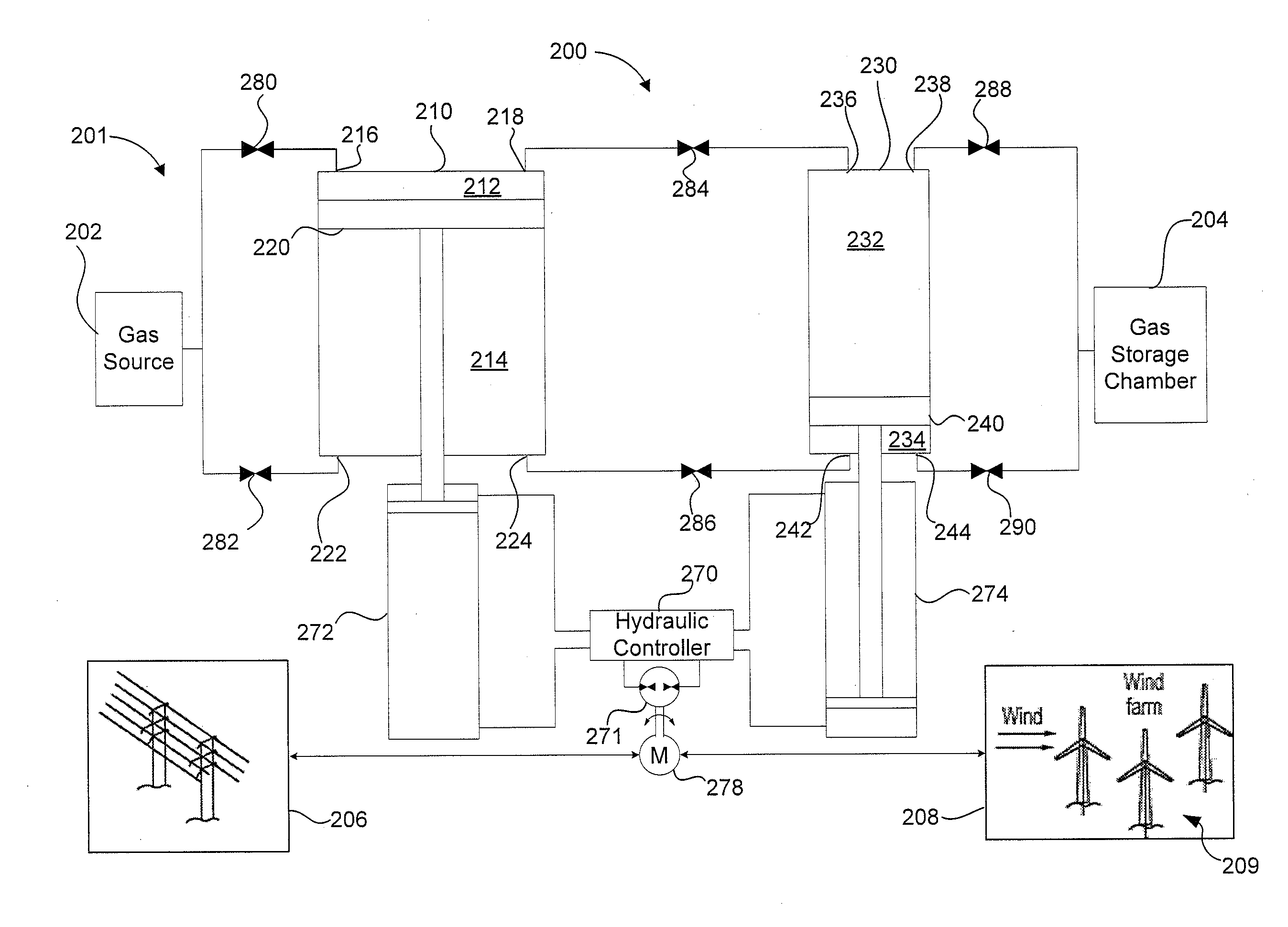
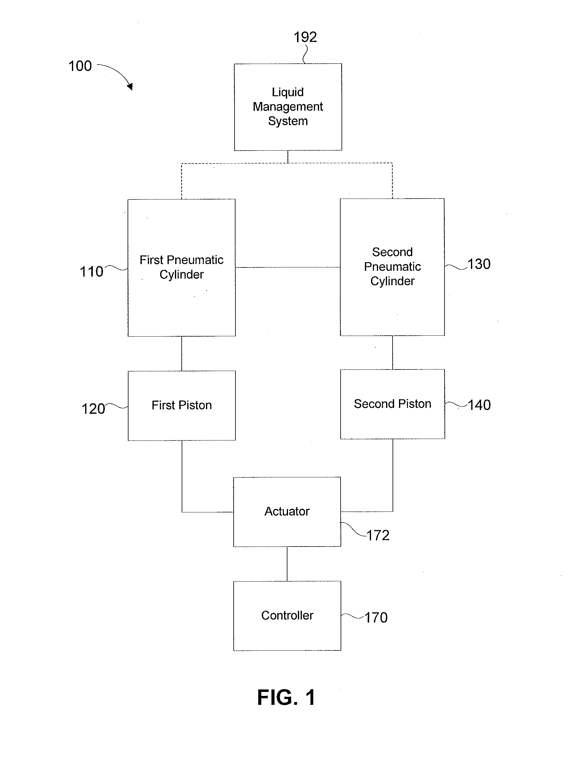
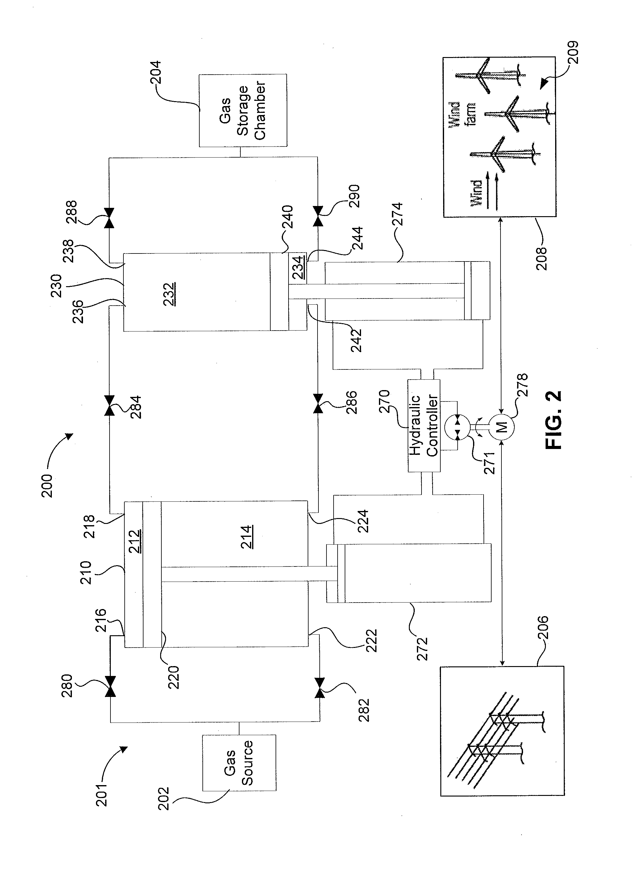
[0017]Systems, devices and methods for optimizing and efficiency operating a gas compression and / or expansion system are disclosed herein. The gas compression and / or expansion systems can include one or more double-acting working pistons movably disposed within a cylinder to compress gas within a working chamber and configured to compress gas when moved in more than one direction. For example, the double-acting piston can be configured to compress gas both when moved in a first direction and when moved in a second direction opposite to the first direction. The gas compression and / or expansion systems can also include one or more double-acting working pistons movably disposed within a cylinder and configured to displace liquid within a working chamber when moved in more than one direction. For example, the double acting piston can be configured to discharge liquid from a first working chamber and draw liquid into a second working chamber when moved in a first direction, and discharge...


PUM


Abstract

Systems, methods and devices for optimizing thermal efficiency within a gas compression system are described herein. In some embodiments, a device can include a first hydraulic cylinder, a second hydraulic cylinder, and a hydraulic actuator. The first hydraulic cylinder has a first working piston disposed therein for reciprocating movement in the first hydraulic cylinder and which divides the first hydraulic cylinder into a first hydraulic chamber and a second hydraulic chamber. The second hydraulic cylinder has a second working piston disposed therein for reciprocating movement in the second hydraulic cylinder and which divides the second hydraulic cylinder into a third hydraulic chamber and a fourth hydraulic chamber. The hydraulic actuator can be coupled to the first or second working piston, and is operable to move the first and second working pistons in a first direction and a second direction such that volume in the hydraulic chambers are reduced accordingly.

Description

CROSS-REFERENCE TO RELATED APPLICATION[0001]This application is related to U.S. Patent Application Attorney Docket No. GCOM-012 / 00US 312615-2042, entitled “Systems and Methods for Compressing and / or Expanding a Gas Utilizing a Bi-Directional Piston and Hydraulic Actuator,” filed on Nov. 11, 2011, the disclosure of which is incorporated herein in its entirety.BACKGROUND[0002]The invention relates generally to systems, devices and methods for the compression and / or expansion of a gas, such as air, and particularly to a system, device and method for optimizing the energy efficiency of a compressed air energy storage system.[0003]Traditionally, electric power plants have been sized to accommodate peak power demand. Moreover, electric power plant sizing must take into account their maximum power output, minimum power output, and a middle power output range within which they most efficiently convert fuel into electricity. Electric power plants are also constrained in terms of how quickly ...

Claims


Application Information

Patent Timeline
IPC IPC(8): F03B15/00
CPCF02C6/16F03D9/028F04B35/008F04B41/06F15B15/1409Y02E60/15F15B1/027F15B15/08Y02E10/72F03D9/17F03D9/257Y02E60/16Y02E70/30
Inventor BLIESKE, MATTHEW
Owner GENERAL COMPRESSION
Why Eureka
Eureka Blog
Learn More