Method for energizing an HF resonant circuit which has an igniter as a component for igniting a fuel-air mixture in a combustion chamber

a technology of resonant circuit and igniter, which is applied in the direction of electric spark ignition installation, machine/engine, etc., can solve the problem of shift of the resonant frequency of the hf resonant circuit which contains the hf igniter, and the component temperature drift of the phase control loop, so as to achieve easy expansion and improve the quality of the hf resonant circuit

Active Publication Date: 2012-03-08
BORGWARNER BERU SYST
View PDF12 Cites 50 Cited by
  • Summary
  • Abstract
  • Description
  • Claims
  • Application Information

AI Technical Summary

Benefits of technology

[0017]The method according to the invention allows the control circuit to react more quickly than a conventional phase control loop. The resonant frequency in the HF resonant circuit is reached more quickly and is maintained with smaller deviations than in the prior art.
[0020]Control deviations which occur by the readjustment in a phase control loop according to the prior art and which may cause overshoots can be prevented according to the invention.
[0021]By avoiding a phase control loop, the method according to the invention can be applied with an electric circuit structure that is simplified as compared with the prior art, with the result that manufacturing costs are saved.
[0026]Appropriately, the current pulses which are supplied to the DC-AC inverter on its primary side are formed as square-wave pulses or approximately as square-wave pulses. As a result, the HF resonant circuit which is, preferably, configured as a series resonant circuit can be easily excited and adjusted to its resonant frequency.
[0027]The method according to the invention can have different embodiments. It utilizes the behavior of an HF resonant circuit, particularly that of an HF series resonant circuit, during the switch-on operation. The transient behavior of the HF resonant circuit is characterized by the roots or zeros points of its transfer function. A transfer function describes the dependency of the output signal of the HF resonant circuit on the input signal thereof, i.e., current pulses or voltage pulses that generate current pulses. An HF resonant circuit which contains an igniter as a component for igniting a fuel-air mixture in the combustion chamber of an internal combustion engine by means of an HF corona discharge usually reacts with a periodic output signal during switch-on, due to the conjugate complex zero points of its transfer function. The zero points of the current or voltage signal which is generated in the HF resonant circuit due to the energization of the latter are the closer to the resonant frequency of the HF resonant circuit the higher the quality of the HF resonant circuit.

Problems solved by technology

This results in a voltage overshoot between the ignition electrode and the walls of the combustion chamber in which the igniter is arranged.
The shift of the resonant frequency of the HF resonant circuit which contains the HF igniter is a major problem in the prior art.
The prior art is to further disadvantage in that the phase control is susceptible to a temperature drift of the components of the phase control loop and to voltage noise.
If frequencies are high, there may additionally be great switching losses of the circuit breakers used in the switching device on the primary side of the transformer when the phase shift between current and voltage increases.

Method used


Image

  • Method for energizing an HF resonant circuit which has an igniter as a component for igniting a fuel-air mixture in a combustion chamber
  • Method for energizing an HF resonant circuit which has an igniter as a component for igniting a fuel-air mixture in a combustion chamber
  • Method for energizing an HF resonant circuit which has an igniter as a component for igniting a fuel-air mixture in a combustion chamber

Examples


Embodiment Construction

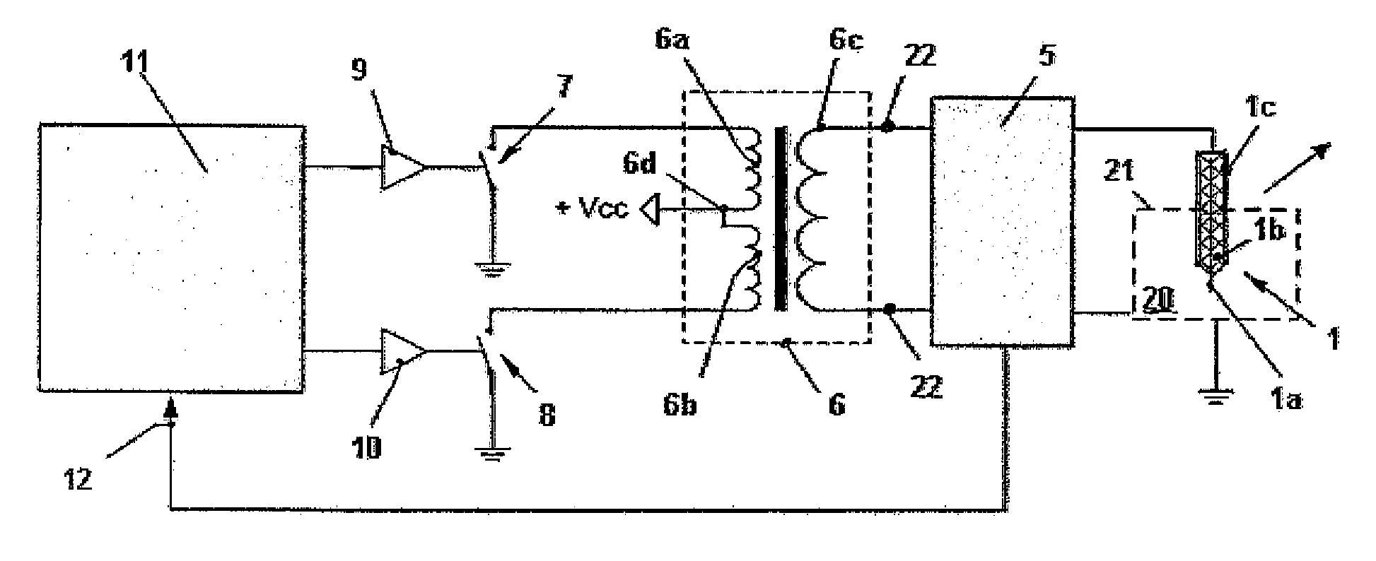
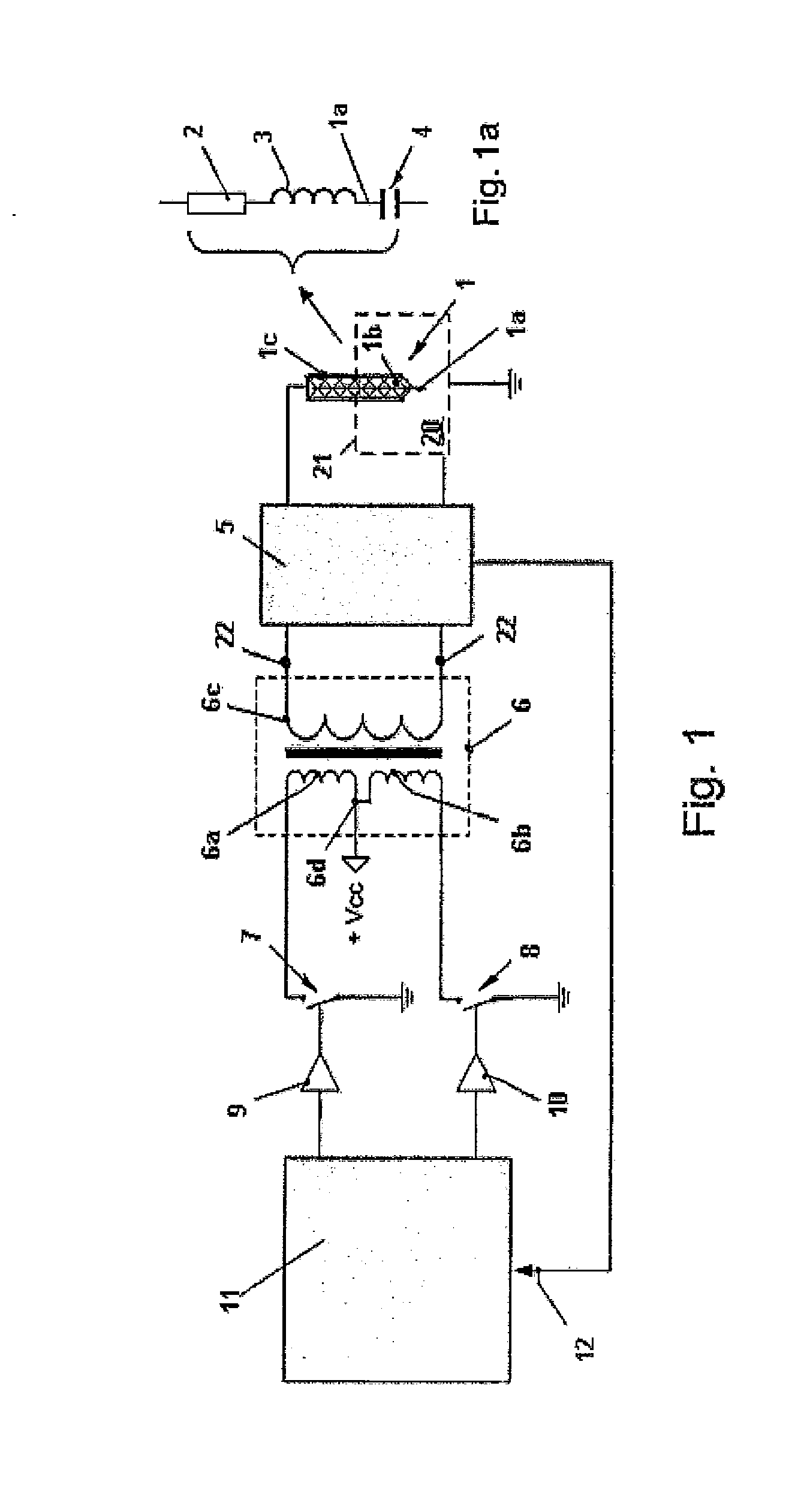
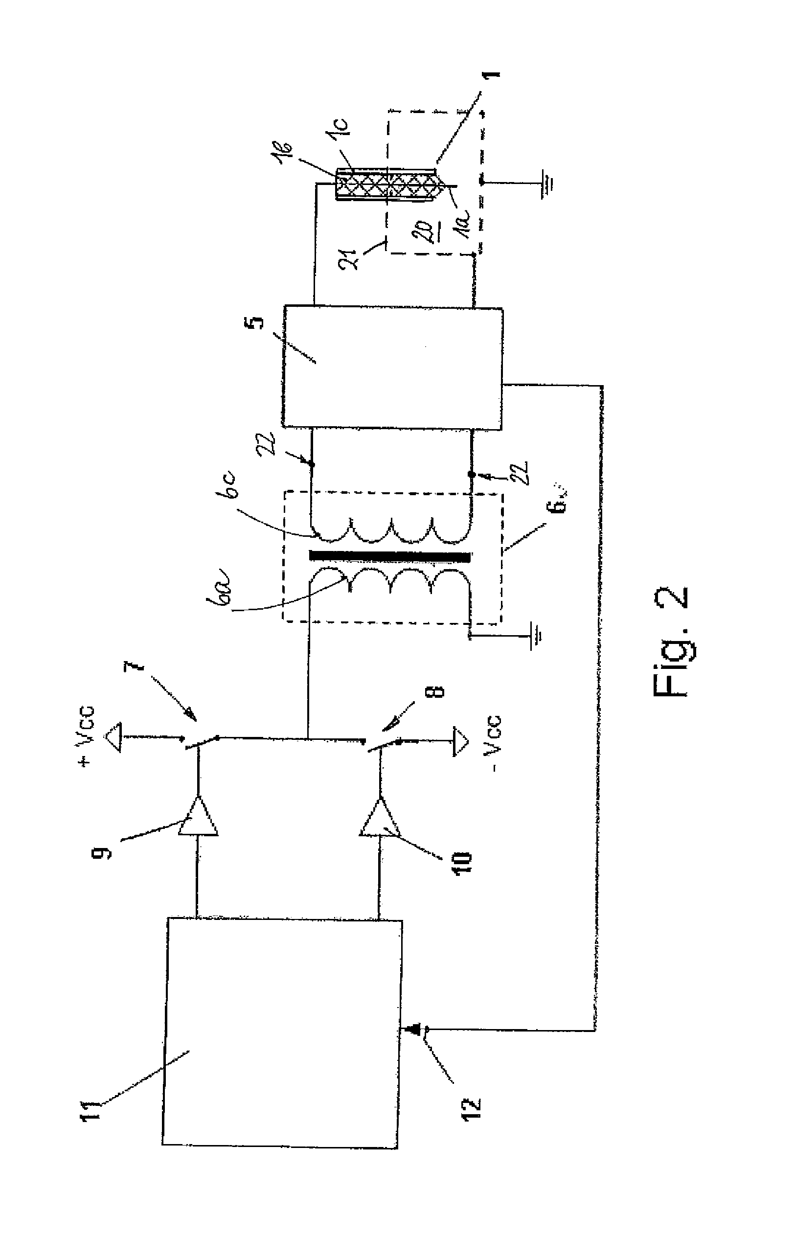
[0049]FIG. 1 shows a combustion chamber 20 which is limited by walls 21 which are applied to ground potential. An HF igniter 1 which comprises an ignition electrode 1a that is surrounded by an insulator 1b along a part of its length projects into the combustion chamber 20. The insulator 1b is surrounded by a metal outer conductor 1c with which the ignition electrode 1a is passed through the wall 21 and into the combustion chamber 20 in an electrically insulating manner. If the igniter 1 does not have a separate outer conductor, the combustion chamber wall 12 can also serve as outer conductor into which the igniter 1 is inserted. The igniter 1 and the walls 21 of the combustion chamber 20 are components of a series resonant circuit which, additionally, consists of a capacitance 4, an inductance 3 and an ohmic resistance 2. As a matter of course, the series resonant circuit can comprise further inductances and / or capacitances and miscellaneous components which are known to persons ski...


PUM


Abstract

The invention relates to a method for energizing an HF resonant circuit which contains an igniter as a component for igniting a fuel-air mixture in a combustion chamber of an internal combustion engine by means of a corona discharge, wherein the igniter comprises an ignition electrode and an insulator surrounding the ignition electrode, by means of a DC-AC inverter which is excited by successive current pulses which each last while a switch controlled by a control circuit is in its conducting switching state. It is provided according to the invention that the switch is actuated when an instantaneous value of an alternating current or an alternating current voltage excited in the HF resonant circuit falls below a first switching threshold (A−, B−, C−) and the switch s actuated when the instantaneous value of the alternating current or the alternating current voltage excited in the HF resonant circuit exceeds a second switching threshold (A+, B+, C+).

Description

[0001]Publications WO 2010 / 011838 A1 and WO 2004 / 063560 A1 disclose how a fuel-air mixture in a combustion chamber of an internal combustion engine can be ignited by an HF corona discharge generated in the combustion chamber. To this end, an ignition electrode of an igniter is passed through one of the walls of the combustion chamber in an electrically insulating manner, the walls being applied to ground potential, and projects into the combustion chamber, preferably opposite a piston provided in the combustion chamber. Along with the walls of the combustion chamber, which are applied to ground potential, the ignition electrode forms a capacitance as a counter electrode. With its content, the combustion chamber acts like a dielectric medium. Depending on the cycle of the piston, air or a fuel-air mixture or an exhaust gas is present in said combustion chamber.[0002]The capacitance is a component of an electric resonant circuit which is energized by means of a high-frequency voltage ...

Claims


Application Information

Patent Timeline
Patent Type & Authority Applications(United States)
IPC IPC(8): F02P3/01
CPCF02P23/04
Inventor RUAN, GANGHUABRAEUCHLE, GERDMUELLER, MARKUS
Owner BORGWARNER BERU SYST
Why Eureka
Try Eureka