Brake system for a motor vehicle

a technology for braking systems and motor vehicles, applied in braking systems, applications and release valves, brake components, etc., can solve the problems of increasing the cost of the braking system, the need for a pump to be constructed, and the relatively powerful, so as to achieve the effect of reducing pressure and building up

Inactive Publication Date: 2011-11-01
LUCAS AUTOMOTIVE GMBH
View PDF19 Cites 0 Cited by
  • Summary
  • Abstract
  • Description
  • Claims
  • Application Information

AI Technical Summary

Benefits of technology

[0017]Furthermore, in another embodiment of the braking system the hydraulic circuit can also have an additional, actively controllable multi-way valve, in particular a two-way solenoid valve, which is interposed between the main brake cylinder and the supply line which leads to the pressure store. This allows the supply of hydraulic fluid from the pressure source or the pressure store to the main brake cylinder to be controlled.
[0018]The two above-mentioned additional, actively controllable multi-way valves thus allow the build-up and reduction of pressure in the main brake cylinder to be controlled in a specific manner by actively controlling and selectively switching between the respective opening and closing positions thereof.

Problems solved by technology

However, this arrangement has the disadvantage that the pump must be constructed so as to be relatively powerful since the pressure differential present at the pump is relatively large.
The pump which must be constructed so as to be correspondingly powerful leads to increased costs for the braking system.
Furthermore, when the pump is driven, the on-board electrical power network is also placed under relatively high loads.

Method used


Image

  • Brake system for a motor vehicle
  • Brake system for a motor vehicle

Examples


Embodiment Construction

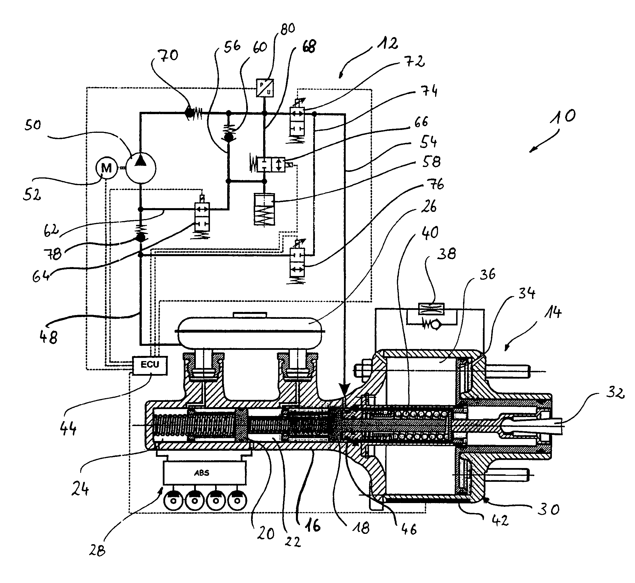
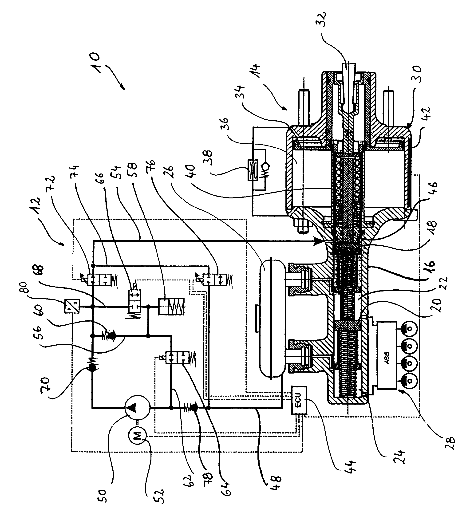
[0022]The FIGURE illustrates a braking system according to the invention which is generally designated 10. The system comprises a hydraulic circuit 12 which provides servo pressure and a brake cylinder assembly 14.

[0023]The brake cylinder assembly 14 comprises a main brake cylinder 16 in which a primary piston 18 is guided so as to be able to be displaced. A secondary piston 20 is further guided so as to be able to be displaced in the main brake cylinder 16 and is mechanically coupled to the primary piston 18 by means of a spring arrangement. The primary piston 18 comprises, with the main brake cylinder 16 and the secondary piston 20, a primary pressure chamber 22. The secondary piston 20 comprises, with the main brake cylinder 16, a secondary pressure chamber 24. The primary pressure chamber 22 and the secondary pressure chamber 24 are coupled in fluidic terms, via respective supply channels, to a hydraulic fluid reservoir 26 for supplying hydraulic fluid in the idle state illustra...


PUM


Abstract

A braking system for a motor vehicle includes a hydraulic circuit for producing a brake force, the hydraulic circuit having a pressure source for producing a hydraulic pressure and a pressure store, the pressure store of the hydraulic circuit being able to be supplied with hydraulic fluid from a delivery side of the pressure source if necessary. In this braking system, there is provision for the pressure store to be able to be coupled in fluidic terms to an intake side of the pressure source by means of an interposed actively controllable multi-way valve, in particular a two-way solenoid valve, and for the pressure store to be able to be decoupled therefrom.

Description

CROSS-REFERENCE TO RELATED APPLICATIONS[0001]This application is a continuation of International Application No. PCT / EP2006 / 006258 filed Jun. 28, 2006, and which claimed priority to German Patent Application No. 10 2005 033 258.7 filed Jul. 15, 2005, the disclosures of which are incorporated herein by reference.BACKGROUND OF THE INVENTION[0002]Various embodiments of a braking system for a motor vehicle are described herein. In particular, a braking system for a motor vehicle includes a hydraulic circuit for producing a braking force, the hydraulic circuit having a pressure source for producing a hydraulic pressure and a pressure store, the pressure store of the hydraulic circuit being able to be supplied with hydraulic fluid from a delivery side of the pressure source if necessary.[0003]A braking system of this type is already known from the prior art. For instance, document DE 103 18 850 A1, and corresponding U.S. Pat. No. 7,296,861 B2, both of which are incorporated by reference h...

Claims


Application Information

Patent Timeline
Patent Type & Authority Patents(United States)
IPC IPC(8): B60T13/16B60T8/40B60T8/44
CPCB60T8/405B60T8/4077B60T8/441B60T13/148
Inventor OHLIG, BENEDIKT
Owner LUCAS AUTOMOTIVE GMBH
Why Eureka
Try Eureka